
Installation Guide

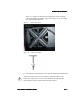
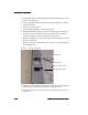
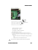
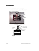
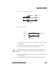
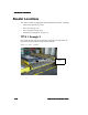
Table Of Contents

ULD Reader Installation
ULD Reader InstallationULD Reader Installation
ULD Reader Installation
ULD Reader Installation Guide
ULD Reader Installation GuideULD Reader Installation Guide
ULD Reader Installation Guide 2-15
2-152-15
2-15
Figure 2-12 Transient Suppressor Connection
Figure 2-13 PC Connection
13. Secure
the
cables
to
the
Strain
Relief
metal
loops,
located
on
the
bottom
of
the
Reader.
14. Reattach
the
Terminal
Access
Panel
on
the
bottom
of
the
Reader.
15. Turn
the
Reader
with
the
top
(Dock
Plate)
facing
up.
A
third
technician
needs
to
be
in
a
position
to
guide
the
Reader
to
the
Bracket
pins
and
help
manage
the
cables
at
the
Access
Panel
end
of
the
Reader.
16. Using
the
lifting
handles,
lower
the
Reader
onto
the
permanently
welded
Reader
Brackets.
17. Secure
the
Reader
to
the
Reader
Brackets
using
Retaining
Bolts
“A”.
To
PC
BLK
-
GND
WHT
-
L3
BLK
-
L1
RED
-
L2
Shield
To
ULD
Reader
BLK
-
8
RED
-
2
BLK
-
5
WHT
-
3
DB9
Female