
Installation Guide
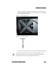
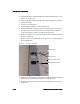
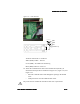
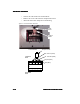
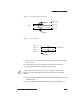
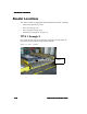
Table Of Contents

ULD Reader Installation
ULD Reader InstallationULD Reader Installation
ULD Reader Installation
2-14
2-142-14
2-14 ULD Reader Installation Guide
ULD Reader Installation GuideULD Reader Installation Guide
ULD Reader Installation Guide
• Connect
the
cable
leads
to
the
terminal
block.
•Remove
the
excess
cable
from
the
compartment
interior.
•Attach
the
strain
relief
and
press
into
the
housing.
Figure 2-11Communication Terminals
Snap-on
Ferrite
Strain
Relief
L4 L3 L2 L1 GND
Transient
Side
RX
-
Data
In
(WHT)
TX
-
Data
Out
(RED)
Program
(BLK)
GND
(BLK)
Snap-on
Ferrite
To
Female
DB-9
Protected
Side