
Installation Guide
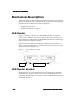
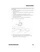
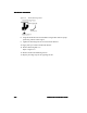
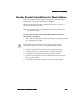
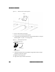
Table Of Contents

ULD Reader Installation
ULD Reader InstallationULD Reader Installation
ULD Reader Installation
2-2
2-22-2
2-2 ULD Reader Installation Guide
ULD Reader Installation GuideULD Reader Installation Guide
ULD Reader Installation Guide
Mechanical Description
The
Reader
and
the
two
Reader
Brackets
securing
it
to
the
conveyor
comprise
the
basic
components
set
for
each
ULD
Reader
system.
This
section
provides
diagrams
and
a
brief
description
of
these
components:
•ULD
Reader on
page
2-2
•ULD
Reader
Bracket on
page
2-2
ULD Reader
Figure
2-1
provides
a
side
view
of
a
ULD
Reader.
Readers
are
installed
between
rollers
and
below
the
conveyor
system.
This
figure
also
shows
the
relationship
between
the
Reader
and
the
ULD
Reader
Brackets
and
Retaining
Bolts
securing
the
components
together.
Different
locations
require
specific
Reader
configurations.
Information
on
where
and
how
many
Readers
are
installed
for
specific
locations
is
covered
in
“Reader
Locations”
on
page 2-18.
Figure 2-1 Savi ULD Reader - Side View
ULD Reader Bracket
The
Reader
rests
on,
and
is
attached
to
the
roller
suspension
rail
with
ULD
Reader
Brackets.
Figure
2-1
shows
a
side
view
of
a
ULD
Reader
Bracket
supporting
a
Reader.
Figure
2-2
on
page 2-3
shows
a
dimensioned
perspective
of
a
Reader
Bracket.
Retaining
Bolt
“A”
Bracket