ULD Reader Installation Guide Singapore Airlines AFT 5
First edition June 2000 Part number 260-02920-001 Rev. B Copyright © 2000 Savi Technology Incorporated. All rights reserved. Printed in the United States of America. Information in this manual is subject to change without notice and does not represent a commitment from the vendor. The software and/or databases described in this document are furnished under a license agreement or nondisclosure agreement. The software and/or databases may be used or copied only in accordance with the terms of the agreement.
Regulatory Approvals Regulatory Approvals Federal Communications Commission (FCC) Notice The Federal Communications Commission has established technical standards regarding radio frequency energy emitted by computer devices. This equipment has been tested and found to comply with the limits for a Class A digital device, pursuant to Part 15 of the FCC Rules. These limits are designed to provide reasonable protection against harmful interference when the equipment is operated in a commercial environment.
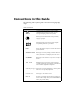
Conventions in this Guide The following table explains guide conventions and typography usage. Guide Conventions Example Meaning and Use Caution notices call attention to the possibility of damaging the product, the system, or your work (for example, potential loss of data). Warning notices call attention to the possibility of injury to people. Ex a le mp Examples provide a scenario to further explain the preceding direction or procedure.
Getting Assistance Getting Assistance If you have trouble with the product, after you have checked your connections and the ULD Reader Installation Guide, contact Savi Technical Support. Technical Support To contact Savi Technical Support: • Telephone 1-888-994-SAVI (North America only) or 1-408-743-8000 between 8:00 a.m. and 5:00 p.m. Pacific Time. • Send an e-mail to help@savi.com.
Getting Assistance vi
Contents Regulatory Approvals . . . . . . . . . . . . . . . . . . . . . . . . . . . . . . . . . . . . . iii Conventions in this Guide . . . . . . . . . . . . . . . . . . . . . . . . . . . . . . . . . . iv Getting Assistance . . . . . . . . . . . . . . . . . . . . . . . . . . . . . . . . . . . . . . . . v Technical Support . . . . . . . . . . . . . . . . . . . . . . . . . . . . . . . . . . . . . v Chapter 1: Introduction Summary . . . . . . . . . . . . . . . . . . . . . . . . . . . . . . . . . . . . . . .
viii ULD Reader Installation Guide
Figures Figure 2-1 2-2 2-3 2-4 2-5 2-6 2-7 2-8 2-9 2-10 2-11 2-12 2-13 2-14 2-15 2-16 2-17 2-18 2-19 2-20 2-21 2-22 2-23 2-24 2-25 2-26 1 Page Savi ULD Reader - Side View . . . . . . . . . . . . . . . . . . . . . . . . . 2-2 ULD Reader Bracket - Perspective View. . . . . . . . . . . . . . . . . 2-3 Reader Bracket and Mounting Bolts . . . . . . . . . . . . . . . . . . . . 2-5 Bracket Mounting Fixture . . . . . . . . . . . . . . . . . . . . . . . . . . . . 2-6 Reader Bracket and Mounting Bolts . . . . . . .
x ULD Reader Installation Guide
1 Introduction 1 This guide provides information for installing Unit Load Device (ULD) Readers for Singapore Airport Terminal Services (SATS) in support of the ULD Tracking System, for tracking cargo pallets and containers. SATS provides cargo handling services for major international airlines in Singapore. There are five Air Freight Terminals (ATF) in operation today, with Terminal 6 currently under construction.
Introduction Summary In AFT5, pallets and containers (ULDs), are handled by a Material Handling System (MHS). They are stored in a multi-level ULD storage system with a capacity of 1316 ULDs within the MHS. Electronic sensors are strategically located on conveyors and equipment to monitor movement of ULDs. Signals are transmitted and analyzed by a DEC VAX mini computer through a comprehensive network.
2 ULD Reader Installation 2 This chapter provides information for installing ULD Readers, including the following topics: • Mechanical Description • Existing Bracket Removal and Reader Bracket Installation • Reader Installation • Installation Tools • Installation Materials • Reader Locations This chapter also provides installation sheets which consist of: • Hardware diagrams for the installation locations • Sign-off fields to be filled out and signed when work is complete for a specific lo
ULD Reader Installation Mechanical Description The Reader and the two Reader Brackets securing it to the conveyor comprise the basic components set for each ULD Reader system. This section provides diagrams and a brief description of these components: • ULD Reader on page 2-2 • ULD Reader Bracket on page 2-2 ULD Reader Figure 2-1 provides a side view of a ULD Reader. Readers are installed between rollers and below the conveyor system.
ULD Reader Installation Figure 2-2 ULD Reader Bracket - Perspective View Bolt “A” hole ULD Reader Installation Guide 2-3
ULD Reader Installation Bracket Removal and Installation Deck plates are removed before installation procedures are performed. Installation procedures include: • Reader Bracket Installation for TTTV, ETV, and BV on page 2-4 • Reader Bracket Installation for Workstations on page 2-7 Removing Deck Plates • To remove a deck plate: 1. Determine the mounting location of the Reader (see “Reader Locations” on page 2-18). 2.
ULD Reader Installation • To remove the existing bracket and install the Reader Bracket for TTTV, ETV, and BV: 1. With open-end and adjustable wrenches, remove the U-bracket from the roller suspension rail. 2. Inspect the bracket mounting holes for any dimension and concentricity anomalies. 3. If required, hand-grind the bracket mounting surface smooth. 4. Clean the bracket mounting surface and mounting holes with Xylene, then wipe clean with alcohol. 5.
ULD Reader Installation Figure 2-4 Bracket Mounting Fixture 8. Align the Reader Bracket until the Roller Tangent Bar indicates proper positioning with the roller tangent. 9. Tighten the mounting bolts to secure the Reader Bracket. 10. Apply three spot welds to the Reader Bracket. 11. Remove Retaining Bolt “A”. Refer to Figure 2-4. 12. Remove the Bracket Mounting Fixture. 13. Repeat preceding steps for the opposing bracket.
ULD Reader Installation Reader Bracket Installation for Workstations This activity consists of removing the existing bracket and installing the Reader Bracket (bracket) at Workstations 1 through 12. You must perform the procedure, “Removing Deck Plates” on page 2-4 before performing this procedure. Note: The existing brackets at the Workstation locations (1 through 12) are welded into place. • To remove the existing bracket and install the Reader Bracket for Workstations 1 through 12: 1.
ULD Reader Installation Figure 2-5 Reader Bracket and Mounting Bolts 6. Place a lock washer on each bolt. 7. Place a nut on each bolt and hand-tighten. 8. Attach the Bracket Mounting Fixture onto the Reader Bracket, using the Retaining Bolt “A” (m10 - 1.5 carriage bolt). Figure 2-6 Bracket Mounting Fixture 9. Align the Reader Bracket until the Roller Tangent Bar indicates proper positioning with roller tangent. 10. Tighten the mounting bolts. 11. Apply three (3) spot welds to the bracket.
ULD Reader Installation 12. Remove the Retaining Bolt “A”. Refer to Figure 2-6. 13. Remove the Bracket Mounting Fixture. 14. Repeat the preceding steps for the opposing bracket.
ULD Reader Installation Reader Installation Reader installation consists of temporarily installing a Reader Housing to ensure proper fit, and installing the Reader. Temporary Reader Housing Installation You need to temporarily install a Reader Housing to verify proper fit before you begin the formal process of installation. • To temporarily install the Reader: 1. Set the sample Reader Housing in place and check for proper alignment. 2. Remove the sample Reader Housing. 3.
ULD Reader Installation Figure 2-7 on page 2-11 illustrates the lifting points where the lifting tools are attached to the Reader. Figure 2-8 on page 2-11 is an example of a single Lifting Handle tool. Figure 2-7 Reader Lifting Points Figure 2-8 Lifting Tool (Handles) 3. Lift the Reader and carefully lower it onto the mounting Reader Brackets. A third technician needs to be in a position to guide the Reader to the bracket pins. These pins are at the Access Panel end of the Reader.
ULD Reader Installation 4. Attach the Reader to the Reader Brackets using Retaining Bolts “A” (see Figure 2-6 on page 2-8). 5. Check for Reader distance from the roller tangent (0.480 -0.5”) at both ends of the Reader. 6. Check for any interference. 7. Remove Retaining Bolts “A” from both brackets. 8. Remove the Reader, and place it with the top (Dock Plate) facing down onto the two 2x4 wooden work blocks for communication and power connection, pulling two meters of cable slack from the pit. 9.
ULD Reader Installation Figure 2-10 Power Terminals WHT GRN BLK Chassis Lug Terminal connections are as follows: White (WHT) or Blue - Term # 1 Green (GRN) - Attached to the chassis lug. Black (BLK) or Brown - Term # 3 12. Attach the communication cable to the terminal block (and PC), as described in the steps below and shown in Figure 2-11, Figure 2-12, and Figure 2-13. • Insert the communication cable through the opening in the bottom cover. • Clamp the Ferrite onto the communication cable.
ULD Reader Installation • Connect the cable leads to the terminal block. • Remove the excess cable from the compartment interior. • Attach the strain relief and press into the housing.
ULD Reader Installation Figure 2-12 Transient Suppressor Connection BLK - GND WHT - L3 To PC BLK - L1 RED - L2 Shield Figure 2-13 PC Connection BLK - 5 WHT - 3 To ULD Reader BLK - 8 RED - 2 DB9 Female 13. Secure the cables to the Strain Relief metal loops, located on the bottom of the Reader. 14. Reattach the Terminal Access Panel on the bottom of the Reader. 15. Turn the Reader with the top (Dock Plate) facing up.
ULD Reader Installation Required Installation Tools This section provides a listing of the required tools to perform the installation tasks outlined in this chapter. These tools include: 2-16 • Acetylene Torch (on-site access) • Adhesives • Arc Welder • Phillips Screwdriver Set • Standard Screwdriver Set • Double Face Tape • Soldering Gun/Pencil • Solder • Hand Grinder w/Misc.
ULD Reader Installation Installation Materials The following materials are required to perform the installation tasks: • 26 ea. Temporary Deck Plates • 52 ea. Mounting Brackets • 104 ea.(3/8 in. diameter) Nuts, Bolts and Washers • A/R, AC Power Cable • A/R, Data Cable • 26 ea. DB-9 Female Connector • A/R, Misc. Wire Lugs/Connectors • 26 ea.
ULD Reader Installation Reader Locations This section consists of photographs illustrating Reader locations, including: • TTTV 1 through 3 on page 2-18 • BV 1 and 2 on page 2-19 • ETV 1 through 3 on page 2-20 • Workstations 1 through 12 on page 2-21 TTTV 1 through 3 Each TTTV location requires two Readers. A Reader is to be placed at the front of the Stops on both the airside and the landside.
ULD Reader Installation BV 1 and 2 Each BV location requires one Reader.
ULD Reader Installation ETV 1 through 3 Each ETV location requires two Readers. A Reader is to be placed at the front of the stops on both the airside and the landside.
ULD Reader Installation Workstations 1 through 12 Each Workstation location requires one Reader.
ULD Reader Installation Installation Sheets The following installation sheets consist of hardware diagrams for the following locations: • TTTV 1, Level 1 on page 2-23 • TTTV 2, Level 1 on page 2-24 • TTTV 3, Level 1 on page 2-25 • BV 1, Level 2 on page 2-26 • BV 2, Level 5 on page 2-27 • ETV 1, Level 1 on page 2-28 • ETV 2, Level 1 on page 2-29 • ETV 3, Level 1 on page 2-30 • Workstation 1 - 12, MCP 1, Level 1 on page 2-31 These installation sheets also consist of sign-off fields to be fi
ULD Reader Installation TTTV 1, Level 1 The Reader is positioned in front of the stops on the airside and the landside.
ULD Reader Installation TTTV 2, Level 1 The Reader is positioned in front of the stops on the airside and the landside.
ULD Reader Installation TTTV 3, Level 1 The Reader is positioned in front of the stops on the airside and the landside.
ULD Reader Installation BV 1, Level 2 This location requires: • 1 Reader • 2 Brackets Figure 2-21 BV 1, Level 2 Hardware Diagram Check list: Station test: Savi Supervisor sign-off: Notes: 2-26 ULD Reader Installation Guide
ULD Reader Installation BV 2, Level 5 This location requires: • 1 Reader • 2 Brackets Figure 2-22 BV 2, Level 1 Hardware Diagram Check list: Station test: Savi Supervisor sign-off: Notes: ULD Reader Installation Guide 2-27
ULD Reader Installation ETV 1, Level 1 The Reader is positioned in front of the stops on the airside and the landside.
ULD Reader Installation ETV 2, Level 1 The Reader is positioned in front of the stops on the airside and the landside.
ULD Reader Installation ETV 3, Level 1 The Reader is positioned in front of the stops on the airside and the landside.
ULD Reader Installation Workstation 1 - 12, MCP 1, Level 1 The Reader is positioned in front of the stops on the airside and the landside.
ULD Reader Installation 2-32 ULD Reader Installation Guide
Index 1 A-B access panels, terminal 2-12 attachment communication cable 2-13 power connections 2-12 Bracket removal and installation 2-4, 2-7 ULD Reader 2-2 Bracket Mounting Fixture 2-8 C communication cable attachment 2-13 EVT 1, Level 1 2-28 EVT 2, Level 1 2-29 EVT 3, Level 1 2-30 Reader 2-18 TTTV 1, Level 1 2-23 TTTV 2, Level 1 2-24 TTTV 3, Level 1 2-25 Workstation 1 - 12, MCP 1, Level 1 2-31 M materials installation 2-17 mechanical description 2-2 N D deck plates removing 2-4 F-G Guide Conventio
support email v telephone v T technical support v terminal access panels 2-12 the 2-10 IX-2 tools installation 2-16 ULD Reader 2-2 ULD Reader Bracket 2-2 U-V writing conventions iv ULD Reader Installation Guide