
User's Manual

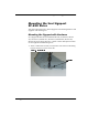
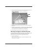
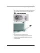
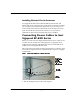
Table Of Contents
- Savi Signpost SP-65X Series Installation Guide
- Contents
- Figures
- Introduction
- Hardware Installation
- Signpost Configuration

&+$37(5
+DUGZDUH,QVWDOODWLRQ
6DYL6LJQSRVW63;6HULHV,QVWDOODWLRQ*XLGH
Using two lengths of plastic chain, attach each at both ends to the four
removable links, as shown in Figure 2-1 and Figure 2-2.
)LJX U H $WWDFKLQJFK DLQ
Attach another removable link to the center of the chain, as shown in
Figure 2-2.
Attach the top removable link to an appropriate rope, cable, or chain and
fasten to a 3/8 inch (.95 cm) eye screw or eye bolt (minimum 1-½ inch
(3.8 cm) penetration into solid material or through bolt).
Secure the power cord to the chain and route, as required.
0RXQWLQJWKH6LJQSRVWZLWK0RXQWLQJ)HHW
Savi Signpost SP-65X Series models SP-650-011, SP-650-111, SP-651-011,
SP-651-111, SP-652-011, SP-652-111, SP-650-101, SP-651-101,
SP-652-101 must be mounted with the supplied mounting feet.
Attach the mounting feet.
Figure 2-3 shows the mounting feet with the self-tapping screws that
attach them to the signpost.
5HPRYDEOH
OLQN
3ODVWLFFKDLQ