
User's Guide

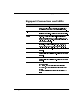
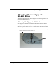
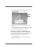
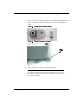
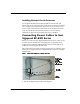
Table Of Contents
- Savi Signpost SP-65X Series Installation Guide
- Contents
- Figures
- Introduction
- Hardware Installation
- Signpost Configuration

&+$37(5
+DUGZDUH,QVWDOODWLRQ
6DYL6LJQSRVW63;6HULHV,QVWDOODWLRQ*XLGH
,QVWDOOLQJ([WHUQDO)HUULWH$QWHQQDV
Savi Signpost SP-65X Series models SP-650-011, SP-651-011, and
SP-652-011 may be equipped with external ferrite rod antennas for indoor
use in compact areas or for special applications. If you are using two or
more external ferrite antennas, mount them at least 10 inches (25.4 cm)
apart. You mount the external ferrite antenna on a C-cross-section
aluminum (or other non-ferrous metal) rod, such as a handrail.
&RQQHFWLQJ3RZHU&DEOHVWR6DYL
6LJQSRVW63;6HULHV
Before you connect the Savi Signpost SP-65X Series power cable, be sure
to check relevant configuration, wiring diagrams, or applicable safety
regulations. The following table details the connectors and LEDs on all
models of the Savi Signpost SP-65X Series.
This section does not include connecting the signpost to a computer with a
serial cable for signpost software configuration. See Chapter 3, “Signpost
Configuration.”
)LJXUH 6LJQSRVWFRQQHFWLRQVZLWKPRXQWLQJKDUGZDUH
Run the appropriate power cable to the signpost.
$QWHQQD
FRQQHFWLRQ
3RZHU56
V\QFLQDQGV\QF
RXWFDEOH
FRQQHFWLRQV
56XVHGIRU
GLDJQRVWLFVRQO\
5-FDE OH
FRQQHFWLRQ