
User's Manual

0RXQWLQJWKH6LJQSRVWV
(FKR3RLQW6LJQSRVW,QVWDOODWLRQ*XLGH
&DEOLQJWKH0RGHO636LJQSRVW
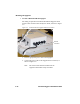
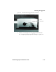
The connectors and LED shown in Table 2-4 are available on a
Model SP-600-101 Signpost.
» To cable a Model SP-600-101 Signpost
1. Cable the Model SP-600-101 the same as the Model SP-600-201.
For cabling, the Model SP-600-101 is identical to the cabling for
the Model SP-600-201 except that the Model SP-600-101 has an
internal antenna.
See “Cabling the Model SP-600-201 Signpost” on page 2-9.
2. Continue with configuration using Signpost Host software.
See “Configuring Signpost Operation Settings” on page 3-3.
7DEOH 0RGHO636LJQSRVW&RQQHFWRUVDQG/('V
Connectors and
LEDs
Description
Power The input power is connected here.
RS-232 Used to connect to a computer for setup and diagnostics by
installers and technicians.
Sync In Used to synchronize 2 to 4 Model SP-600-101 Signposts to cover
an area larger than is possible with a single Signpost. This
connector can also accept DC volts from another Signpost to avoid
running separate power lines when two or more Signposts are
synchronized
Sync Out Used to synchronize 2 to 4 Model SP-600-101 Signposts to cover
an area larger than is possible with a single Signpost. This
connector can also output DC volts to another Signpost to avoid
running separate power lines when two or more Signposts are
synchronized
Sensor 1 A closure on these two pins will trigger a predefined Signpost
action.
Sensor 2 A closure on these two pins will trigger a predefined Signpost
action.
Status This LED indicates when power is applied and the Signpost mode
of operation.
On ½ second, off ½ second indicates normal operation
On 1 second, off 1 second indicates the Signpost is off but powered
On continuously indicates the Signpost is transmitting a CW signal