Micro Reader MR-1 User Manual Document Number : 090-01-001-DOC Rev C2 Last Changed : 18 January 2022 Author : Tai Wai Pong Copyright SATO Vicinity 2022 Commercial in Confidence
Table of Contents 1. 2. 3. 4. 5. Overview ....................................................................................................................... 1 Features and Benefits................................................................................................... 2 Specifications ............................................................................................................... 2 Dimensions ....................................................................................
FCC Radio Frequency Interference Statement (USA) The FCC regards RFID equipment as low-power transmitting devices and, therefore, does not require users of RFID devices to obtain a license to operate them. NOTE: This equipment has been tested and found to comply with the limits for a Class B digital device, pursuant to Part 15 of the FCC Rules. These limits are designed to provide reasonable protection against harmful interference in a residential installation.
1. Overview The MR-1 is the smallest and simplest of Magellan’s reader modules. It is intended for Original Equipment Manufacturer (OEM) applications where it is typically embedded in an RFID enabled product. Examples include printers, hand held readers, data capture terminals, low cost desktop readers, identification and access controls.
2. Features and Benefits Low power module easy to build into RFID enabled equipment. Small footprint. Simple Serial UART interface. Simple Antenna connection. 3. Specifications Electrical Operating Frequency 13.56MHz ISO/IEC Compliance ISO/IEC 18000-3 Mode 2 Command Data Rate 424 kbit/s Reply Data Rate 106 kbit/s Number of Reply Channel 1 (Channel ‘G’) Number of Axes 1 Power Supply +5.0 ± 0.
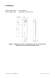
4. Dimensions 4.0 56.0 60.0 60.0 Figure 3 : Major Module Dimensions (mm) Mounting Holes 4x 3.
5. Connections 5.1 J1 - Host Connector Connector Type 10 pin (JST Model S10B-PH-K-S) Reference: http://www.jst-mfg.com/product/pdf/eng/ePH.pdf Pin Number Function 1 +5 Vdc 2 +5 Vdc 3 Ground 4 Ground 5 6 RxD UART Receive Signal (+5V TTL/ +3.3V LVCMOS) Input to module. TxD UART Transmit Signal (+5V CMOS) Output from module. 7 Not Connected 8 Not Connected 9 Not Connected 10 Not Connected 5.2 J2 - Antenna Connector Connector Type 2 pin (JST Model S2B-PH-K-S) Reference: http://www.jst-mfg.
6. Antenna Antenna Cable Length Antenna Cable Types 50 cm maximum Twisted Pair or 50 Ohm co-ax. Figure 4 : Dimensions of 090-10-010-ASY Ver: A 6-Turn Antenna (mm) (Equivalent for unit in SATO CG208 Printer).
Antenna Cable Length Antenna Cable Types 50 cm maximum Twisted Pair or 50 Ohm co-ax 4 - Ø5.5 10.50 92.00 5.0 17.00 9.5 5.0 Figure 5 : Dimensions of 090-10-005-ASY Ver: A 6-Turn Antenna (mm) (Equivalent for unit in SATO CL4XX and CL4NX Printer). ©2015 SATO Vicinity. All rights reserved. Specifications subject to change without notice. Any unauthorized reproduction of the contents of this presentation, in part or whole, is strictly prohibited.