SATEC POWERMETERS SATEC COMMUNICATION DRIVER FOR ALLEN-BRADLEY SLC 500 1746-BAS BASIC MODULE Installation and Operation Manual SATEC Ltd.
The driver is provided "as is" without any warranty of any kind. The entire risk to the results is assumed by the user. Those responsible for applying and using this product must satisfy themselves as to the acceptability of each application and the use of the product. No patent liability is assumed by the manufacturer with respect to the use of information, circuits, equipment or software described in this text.
Table of Contents 1 ABOUT THE COMMUNICATION DRIVER .............................................................4 2 INSTALLATION ..................................................................................................5 2.1 EPROM Installation......................................................................................5 2.2 BASIC Module Port PRT2 Configuration .........................................................5 2.3 Configuring M0-M1 Files and I/O Words Using APS Software.............
1 ABOUT THE COMMUNICATION DRIVER • The driver provides data exchange between SLC 5/02, 5/03 and 5/04 modular controllers, and SATEC Powermeters via the 1746-BAS BASIC module. • The EPROM firmware versions can be supplied for 1 to 31 instruments. Three data sets and three baud rates (1200, 2400 and 9600 baud) are available upon order. For available data sets, refer to Appendix A.
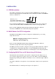
2 INSTALLATION 2.1 EPROM Installation The SATEC communication driver is supplied in 32 Kbyte EPROM memory modules (the memory module designation is 1747-M4). The version of the driver is marked on the EPROM label by a combination of: X - XX - X Data set (1, 2, 3) The number of instruments (1-31) Baud rate (1=1200, 2=2400, 9=9600) Before installing the EPROM memory module in the memory module socket, configure the socket for the 1747-M4 (32 Kbyte UVPROM) memory module by setting jumper JW3.
2.4 Powermeters Communications Settings The Powermeters should be configured properly to operate with the BASIC module. The Powermeters communications settings must be compatible with the BASIC module port PRT2 interface settings (RS-422/485/232) and the driver EPROM version used. The Powermeter communications settings are as follows: • ASCII 422, ASCII 485 or ASCII 232 mode, according to the interface used. • Software handshake. • Baud rate 1200, 2400 or 9600, according to the driver EPROM version used.
3 GENERAL OPERATION 3.1 Interfacing to the BASIC Module The BASIC module interfaces with the SLC processor via the SLC backplane interface. Data is transferred through SLC CPU Module M0 and M1 files as 16-bit signed integers up to 32767. The data to be sent to the BASIC module must be placed in the M0 file. The size, configuration, and contents of the M0 file are discussed in Section 4.2. The data to be sent to the CPU is placed into the M1 file. There are three user-selectable formats of data exchange.
4 APPLICATION INFORMATION 4.1 Acquiring Data From the BASIC Module 4.1.1 General The driver reads measured values from the Powermeters and transfers them to the SLC CPU via M1 file in suitable format. There are three versions of the driver available that have different data sets being transmitted to the CPU. The CPU M1 file structures are shown in Appendix A. To transfer numbers greater than 32767 or between 0 and 1, a special technique is used.
° Examples: 1. The phase A reactive power of value 130,750 kvar is transferred as: word 34 = 750 word 35 = 13 word 36 = 0 The actual value is 13*10000 + 750 = 130,750 2. The phase A reactive power of value -130,750 kvar is transferred as: word 34 = 750 word 35 = 13 word 36 = 1 The actual value is - (13*10000 + 750) = -130,750 Total active power is transferred only for positive values. In the case of the negative total power, the value will be zeroed. 4.1.
Table 4-1 Error Codes Error code (word 64) 0 1 2 Description No errors found The instrument doesn't respond Check error (framing or check field error is detected) 4.2 Writing Data to the BASIC Module The driver allows the CPU to reset accumulated energies and demands in the selected Powermeter, or synchronously in all Powermeters on line, if this function is supported by the instruments. The CPU request is transmitted to the BASIC module via the CPU M0 file.
4.3.2 Data transfer from the BASIC module to the CPU Table 4-4 explains the transfer algorithm in a form of the state machine. Table 4-4 Data transfer through the CPU M1 file CPU input status A=0 A=1 A=1 A=0 A=0 CPU output status B=0 B=0 B=1 B=1 B=0 SLC action BASIC module action Comment No action B:=1 No action A:=1 No action 1. Transfers data to M1 file 2. A:=0 No action Request to send Clear to send 1. Copies M1 file to data file 2.
4.4 Sample Ladder Program This section offers a sample SLC 500 ladder program that communicates with the BASIC module driver and implements handshaking described above. The ladder program diagram is shown in Appendix B. The program assumes the following: 1. The BASIC module slot number is 6. 2. The data file N7 is used for output. The CPU command words is written into words N7:0 and N7:1. 3. Bit B3/0 is used for triggering the CPU command output to implement one-shot write to the BASIC module. 4.
5 TROUBLESHOOTING This chapter describes common problems you might encounter during installation of the communication driver, and offers suggestions for corrective action. It is recommended that you apply a sample ladder program discussed in Section 4.4 for testing the CPU-BASIC module interface operation. With this program you can monitor the data exchange between the CPU and the BASIC module through the CPU data files.
The BASIC module doesn't interface to the instruments The symptom that indicates a problem is that a non-zero error code is received by the CPU in word 64 in the M1 file. It might be reported for all or some of the Powermeters connected to the BASIC module . Note that for the disconnected instruments, that would be a normal response. If you encounter that the problem exists for all the instruments, determine whether one of the following is the cause: 1.
6 ORDERING INFORMATION The ordering number is formed by a combination of: AB 1746-BAS DRIVER VERSION X - XX - X Data set (1, 2, 3) The number of instruments (1-31) Baud rate (1=1200, 2=2400, 9=9600) Example: order for 16 instruments, data set #2, 9600 baud: AB 1746-BAS DRIVER VERSION 2-16-9 15
APPENDIX A DATA SETS Table A-1 Data set #1 Field No.
Table A-2 Data set #2 Field No.
Table A-3 Data set #3 Field No.
APPENDIX B SAMPLE SLC 500 DATA TRANSFER PROGRAM | SLC CPU -----> BASIC module | | | | C D D | | I:6 O:6 B3 O:6 | +--]/[---]/[---] [-------------------------------( L )---------+ | 16 16 0 16 | | | | C D +- COP --------+ | | I:6 O:6 |COPY FILE | | +--] [---] [-------------------+---- |Source #N7:0 |--- +---- + | 16 16 | |Dest #M0:6.
APPENDIX C CABLE DRAWINGS C.
C.2 RS-422 Cable Configuration C.2.1 RS-422 Connection 1746-BAS BASIC module Series PM-280/288/270/290 Powermeters 2 DB9 male connector 3 6 7 1 RxD' TxD RxD TxD**R3 RxD- DB9 male connector 7 8 9 1 TxD **R4 GND Series PM-290H Powermeters 6 TxD' R1 RxD COM 6 9 2 1 5 DB9 female connector TxD RxD TxDRxDGND Series PM-170 Powermeters 14 DB25 male connector 15 16 17 1 TxD RxD TxDRxDGND *R2 R1,R2 - 120 Ω R3,R4 - 1.
C.2.
C.3 RS-485 Cable Configuration C.3.
C.3.