ezPAC™ SA300 Series SUBSTATION AUTOMATION UNIT SA310/SA320/SA330 Installation Manual BG0325 Rev.
LIMITED WARRANTY The manufacturer offers the customer an 24-month functional warranty on the instrument for faulty workmanship or parts from date of dispatch from the distributor. In all cases, this warranty is valid for 36 months from the date of production. This warranty is on a return to factory basis. The manufacturer does not accept liability for any damage caused by instrument malfunction.
Table of Contents Chapter 1 Introduction ........................................................................................... 1 1.1 About This Manual ................................................................................................... 1 1.2 About The SA300 ...................................................................................................... 1 Chapter 2 Installation ............................................................................................. 4 2.
Chapter 1 Introduction 1. Introduction 1.1 About This Manual This manual is intended to assist the user in the installation of the SA300 Series (ezPAC™) Substation Automation Unit. The term ‘SA300’ is used herein to refer to all models in the series. This chapter gives an overview of this manual and an introduction to the SA300. Chapter 2, Installation, provides instructions for mechanical and electrical installation.
• Programmable Controller (32 control setpoints, OR/AND logic, extensive triggers, programmable thresholds and delays, relay control, event-driven data recording). Ability to block relay outputs with a special control algorithm.
Remote Displays The SA300 can be ordered with an optional LED Remote Display Module (RDM) or LCD Remote Graphical Module (RGM). Both have a fast RS-485 port and communicate with the SA300 through the Modbus RTU protocol. Remote displays can be located at distances of up to 0.5 km from the device. The RGM can also be ordered with an Ethernet 10Base-T port and can communicate with the SA300 through a local network. The RDM has three six-digit windows with bright red LEDs well suited for dark areas.
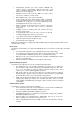
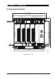
Chapter 2 Installation 2. Installation 2.1 Mechanical Installation 284.00 (11.181") 269.00 (10.590") CURRENT INPUTS + --I 1 1 + --I 2 - 2 3 + --I 3 - 4 5 6 7 J12 1 8 2 3 4 5 6 7 8 PLUG-IN MODULE 1 2 3 4 5 6 7 8 9 10 11 12 13 14 15 16 17 18 19 20 1 2 3 4 5 6 7 8 9 10 11 12 13 14 15 16 17 18 19 20 IRIG-B 4.7 MODEM 1 KEY SWITCH + 1 2 3 4 5 1 BACKUP BATTERY COM3 RDM P.SUPPLY RS-485 J2 4 VDC MEASURE VOLTAGE INPUTS J9 8 IR-PORT JP3 J7 .185"DIA.
Figure 2-1b Mounting Chapter 2 Installation 5
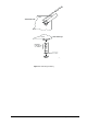
ezPAC LL PU View from side T OU ezPAC LY E US View from top BATTERY AA BATTERY LITHIUM AA 3.
The ezPac display module is connected to the communication connector of the SA300 unit as shown in Figure 2-2.
2.2 Electrical Installation 2.2.1 Power Source Connection The SA300 unit has two independent power supplies: main and backup. The standard power supplies may be connected to an 85-265V AC or 88-290V DC power source. Lower voltage DC power supply options are also available (see Appendix: Technical Specifications). The main power supply connections are: AC power: line to terminal J10 5; neutral to terminal J10 6. DC power: positive to terminal J10 5; negative to terminal J10 6.
K + LINE 1 (A) LINE 2 (B) LINE 3 (C) CT L - LOAD L K + - SW1 Shorting Switches CURRENT INPUTS: SA310 150A SA320 150A + --I 1 - + --I 2 - + --I 3 - + --I 4 1 J12 COM1 JDR1 2 4 5 6 J3 9 7 1 8 +Tx -Tx +Rx -Rx J1 1 2 3 4 5 RS-422/RS-485 2 2 1 2 3 4 5 RS-422/RS-485 IRIG-B MODEM J7 NOT CONNECTED 3 4 5 6 7 8 J14 COM2 +Tx -Tx +Rx -Rx RS-232 5 1 6 3 4 1 JP3 USB ETHERNET 1 J11 J5 3 4 8 COM3 RDM P.
K CT L + K + LINE 1 (A) LINE 2 (B) LINE 3 (C) N L - LOAD L K + - L K + - Shorting Switches SW1 CURRENT INPUTS: SA310 150A SA320 150A + --I 1 - + --I 2 - + --I 3 - + --I 4 - J12 COM1 JDR1 2 1 3 4 5 6 7 1 8 2 NOT CONNECTED 3 4 5 6 7 8 J14 6 COM2 +Tx -Tx +Rx -Rx RS-232 5 1 J3 9 -Tx +Tx +Rx -Rx J1 1 2 3 4 5 RS-422/485 IRIG-B MODEM J7 2 1 2 3 4 5 RS-422/485 4 1 JP3 USB ETHERNET 1 J11 J5 3 4 8 COM3 RDM P.
K + LINE 1 (A) LINE 2 (B) LINE 3 (C) N +- + - +- +- + - +- CT L - L K + - LOAD L K + - L K + - PT Shorting Switches SW1 CURRENT INPUTS: SA310 150A SA320 150A + --I 1 - + --I 2 - + --I 3 - + --I 4 - J12 COM1 JDR1 2 1 3 4 5 6 7 1 8 2 NOT CONNECTED 3 4 5 6 7 8 J14 6 COM2 +Tx -Tx +Rx -Rx RS-232 5 1 J3 9 -Tx +Tx +Rx -Rx J1 1 2 3 4 5 RS-422/485 IRIG-B MODEM J7 2 1 2 3 4 5 RS-422/485 1 4 JP3 USB ETHERNET 1 J11 J5 3 4 8 COM3 RDM P.
RELAY CTs +- +- +- +- +- +- METER CTs L K + LINE 1 (A) LINE 2 (B) LINE 3 (C) N - - L K + L K + - L K + - L K + - L K + LOAD L K + - - K + - L PT Shorting Switches SW1 CURRENT INPUTS SA330 150A + - + --I 5 I 6 - + --I 1 - + --I 2 - + --I 3 - + --I 4 1 J12 COM1 JDR1 2 3 4 5 6 7 1 8 2 4 3 + - + -I 7 -I 8 5 6 7 CURRENT INPUTS SA330 20A 8 J14 6 COM2 +Tx -Tx +Rx -Rx RS-232 5 1 J3 9 -Tx +Tx +Rx -Rx J1 1 2 3 4 5 RS-422/485 IRIG-B MODEM J7 2 1 2 3
K + LINE 1 (A) LINE 2 (B) LINE 3 (C) CT L - LOAD L K + - + -+ - PT Shorting Switches + -+ - SW1 CURRENT INPUTS: SA310 150A SA320 150A + --I 1 - + --I 2 - + --I 3 - COM1 JDR1 2 1 J12 3 4 5 6 7 1 8 2 4 3 5 6 7 8 J14 6 COM2 +Tx -Tx +Rx -Rx RS-232 5 1 J3 9 +Tx -Tx +Rx -Rx J1 1 2 3 4 5 RS-422/485 IRIG-B 1 2 3 4 5 RS-422/485 MODEM J7 2 1 USB ETHERNET 1 J11 J5 3 4 8 COM3 RDM P.
RELAY CTs METER CTs L K + LINE 1 (A) LINE 2 (B) LINE 3 (C) L K + - - L K + LOAD L K + - - + -+ - PT + -+ - SW1 Shorting Switches CURRENT INPUTS SA330 150A CURRENT INPUTS SA330 20A + --I 1 - + --I 2 - + --I 3 - COM1 JDR1 2 1 J12 3 4 5 6 7 + --I 5 1 8 2 -I 75 6 + 4 3 8 7 J14 6 COM2 +Tx -Tx +Rx -Rx RS-232 5 1 J3 9 +Tx -Tx +Rx -Rx J1 1 2 3 4 5 RS-422/485 IRIG-B MODEM J7 2 1 2 3 4 5 RS-422/485 1 4 JP3 USB 1 ETHERNET J11 J5 3 4 8 COM3 RDM P.
K + LINE 1 (A) LINE 2 (B) LINE 3 (C) N +- +- +- +- CT L - L K + - LOAD L K + - PT Shorting Switches SW1 CURRENT INPUTS: SA310 150A SA320 150A + --I 1 - + --I 2 - + --I 3 - + --I 4 - J12 COM1 JDR1 2 1 3 4 5 6 7 1 8 2 NOT CONNECTED 3 4 5 6 7 8 J14 6 COM2 +Tx -Tx +Rx -Rx RS-232 5 1 J3 9 -Tx +Tx +Rx -Rx J1 1 2 3 4 5 RS-422/485 IRIG-B MODEM J7 2 1 2 3 4 5 RS-422/485 1 4 JP3 USB ETHERNET 1 J11 J5 3 4 8 COM3 RDM P.
RELAY CTs +- +- +- +- METER CTs L K + LINE 1 (A) LINE 2 (B) LINE 3 (C) N - L K + - L K + - L K + L K + - - LOAD L K + - PT Shorting Switches SW1 CURRENT INPUTS SA330 20A CURRENT INPUTS SA330 150A + --I 1 J12 COM1 JDR1 2 1 4 5 6 7 J3 9 8 1 -Tx +Tx +Rx -Rx J1 1 2 3 4 5 RS-422/485 IRIG-B 2 1 2 3 4 5 RS-422/485 MODEM JP3 J7 -I 63 4 + -I -7 5 6 + 7 8 J14 COM2 +Tx -Tx +Rx -Rx RS-232 5 1 6 3 -I -5 -2 + - + --I 2 - + --I 3 - + --I 4 - 1 4 USB ETHERN
K + LINE 1 (A) LINE 2 (B) LINE 3 (C) CT L - L K + - LOAD L K + - + -+ - PT Shorting Switches + -+ - SW1 CURRENT INPUTS: SA310 150A SA320 150A + --I 1 - + --I 2 - + --I 3 - + --I 4 - J12 COM1 JDR1 2 1 3 4 5 6 7 1 8 2 NOT CONNECTED 3 4 5 6 7 8 J14 6 COM2 +Tx -Tx +Rx -Rx RS-232 5 1 J3 9 +Tx -Tx +Rx -Rx J1 1 2 3 4 5 RS-422/485 IRIG-B MODEM J7 2 1 2 3 4 5 RS-422/485 1 USB ETHERNET 1 J5 J11 3 4 8 COM3 RDM P.
RELAY CTs METER CTs L K + LINE 1 (A) LINE 2 (B) LINE 3 (C) - L K + - L K + - L K + L K + - - LOAD L K + - + -+ - PT + -+ - Shorting Switches SW1 CURRENT INPUTS SA330 20A CURRENT INPUTS SA330 150A + - + --I 5 I 6 - + --I 1 - + --I 2 - + --I 3 - + --I 4 1 J12 COM1 JDR1 2 3 4 5 6 7 1 8 2 4 3 + -I 7 5 6 7 8 J14 6 COM2 +Tx -Tx +Rx -Rx RS-232 5 1 J3 9 +Tx -Tx +Rx -Rx J1 1 2 3 4 5 RS-422/485 IRIG-B MODEM J7 2 1 2 3 4 5 RS-422/485 1 4 JP3 USB ETHERNET
* L 1 (A) LINE 1 (A) K CT L - + * 240VAC L 2 (B) LINE 2 (B) 240VAC 240VAC LINE 3 (C) * L3 LOAD (C) 120VAC N - + 208VAC L K 120VAC L K - + N N Shorting Switches SW1 Grounded delta connection 208V * L 2 (B) 240V 240V * L 1 (A) 120V 120V N * L 3 (C) CURRENT INPUTS: SA310 150A SA320 150A + -I -1 1 J12 COM1 JDR1 2 3 4 5 6 J3 9 7 8 1 -Tx +Tx +Rx -Rx J1 1 2 3 4 5 RS-422/485 IRIG-B 2 2 1 2 3 4 5 RS-422/485 MODEM J7 4 3 5 6 7 8 J14 COM2 +Tx -Tx +Rx -
2.2.6 Digital Inputs There are two possible module types: a) 16 Digital Inputs, b) 16x2 (32) Digital Inputs. Optically isolated digital inputs in one digital input module are provided for status monitoring and external synchronization of power demand period and time. Dry or wet contacts may be connected to these inputs, as shown in Figures 2-10, 11, 12, and 13.
Wet Contacts Wet contact options are: 24V, 48V, 125 , 250 VDC (voltage varies according to wet contact option). + 125V DC 10A FUSE 1 SA300 2 3 LOAD 1 1 2 2 3 3 4 4 C 1-4 5 5 6 6 7 7 8 8 9 C 5-8 10 9 11 10 12 11 13 12 14 C 9-12 15 13 16 14 17 15 18 16 19 C 13-1620 LOAD 4 1 INPUTS 125/250V DC LOAD DI DIGITAL 125/250V DC - 1 LOAD + 120V DC 10A FUSE 2 11 LOAD 12 LOAD 13 14 LOAD LOAD 02-04025 Figure 2-12 16-DI Digital Input Connection for Wet Contacts.
Relays There are two possible variants: a) 8 relays in one Relay Output Module. b) 8x2 (16) relays in one Relay Output Module. These output are provided for alarms, remote control or energy pulsing, as shown in Figure 2-14 and 15. For ratings, see Appendix: Technical Specifications.
2.2.7 Analog Output The SA300 provides 4 optically isolated analog inputs and 4 analog outputs with internal power supplies. Current output options are: 0-20 mA and 4-20 mA (current loop load of up to 500 Ohm), 0-1 mA and ±1 mA (current loop load of up to10 kOhm), as shown in Figure 2-16.
2.2.8 DC Voltage Input SA300 models are provided with one DC voltage input, which can be used for measuring of substation storage battery voltage (see Figure 2-17a), or for measuring unit power supply voltage (see Figure 2-17b). Copper wiring 1.5-2.5 mm2 (15 –13 AWG) should be used.
Communications + - - UP TO 31 UNITS UP TO 31 UNITS 5 6 9 + - + + Tx Rx Tx 1 RS-485 - + + RS-485 COM1 RS-232 COM2 Rx - + + Tx Rx Tx - Rx J1 1 2 3 4 5 J3 1 2 3 4 5 JDR1 - + + - PC 1 RS-485 POWERMETER + PC 2 RS-485 POWERMETER + 2.2.9 RS-422/485 RS-422/485 SA300 02-04021 ezPAC (01-12024) Figure 2-18 Communication Network Connection – RS-422/RS-485 2.
Chapter 3 Communications 3.
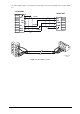
Computer Connections – RS-232 Figure 3-2 RS-232 Hardware Handshaking Connection , 9-pin Figure 3-3 RS-232 Hardware Handshaking Connection , 25-pin Figure 3-4 RS-232 Simple 3-wire Connection , 9-pin female Figure 3-5 RS-232 Simple 3-wire Connection, 25-pin Chapter 3 Communications 27
External Modem Connections Figure 3-6 RS-232 Simple 3-wire Connection, 9-pin male Figure 3-7 RS-232 Simple 3-wire Connection, 9-pin Initialization String: ATS0=1&D0&K0&W0 28 Chapter 3 Communications
Computer Connections – RS-422/RS-485 Figure 3-8 RS-422 Multidrop Connection, 25-pin PC Port Figure 3-9 RS-485 Multidrop Connection, 25-pin PC Port Chapter 3 Communications 29
Figure 3-10 RS-422 Multidrop Connection, 9-pin PC Port Figure 3-11 RS-485 Multidrop Connection, 9-pin PC Port 30 Chapter 3 Communications
Figure 3-12 RS-485 Multidrop Connection, 9-pin PC Port Figure 3-13 RS-485 Multidrop Connection, 25-pin PC Port Chapter 3 Communications 31
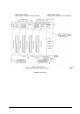
Chapter 4 Changing the Battery 4. Changing the Battery When the battery level drops below the minimum allowed threshold, the red MEM.BAT.LOW LED on the front of the device is lit up, indicating that the battery should be replaced. Use the following procedure: 1. Use a flat screwdriver to open the battery compartment, turning counter-clockwise. 2. Remove the battery cover and the battery 3. Replace the battery - with the plus towards the outside - and close the compartment.
Appendix: Technical Specifications Appendix: Technical Specifications Environmental Conditions Operating Temperature: -20°C to 60°C (-4°F to 140°F) Storage Temperature: -25°C to 80°C (-13°F to 176°F) Humidity: 0 to 95% non-condensing Construction Overall Dimensions Length: 284.00 mm (11.181 Inches) Width: 255.24 mm (10.05 Inches) Depth: 185.00 mm (7.28 Inches) Weight: 5.0kg (11.02 Lb) Materials Enclosure: Cold rolled Steel Panels I/O: Aluminum Face Plates with Graphics: Polycarbonate film PCB.
Terminals Pitch: 9.5 mm Standard AC Current Inputs: I1, I2, I3, I4 Input via CT with 5A secondary Operating range: continuous 20A RMS (ANSI C12.20) or 10A RMS (IEC687) Fault Currents: up to 150A RMS (30x) Burden: < 0.15 VA Overload Withstand: 20A RMS continuous, 250A for 1 second 2 Wire Size: 10 AWG (2.5 to 6 mm ) Terminals Pitch: 13 mm Input via CT with 1A secondary Operating Range: continuous 4A RMS (ANSI C12.20) or 2A RMS (IEC687) Fault Currents: up to 30A RMS Burden: < 0.
16-DI optically isolated, wet contact sensing: External Power Supply: 48 VDC Sensitivity: open @ voltage<14.4 volts, closed @ voltage>33 volts 2 Wire Size: 12 AWG (up to 2.5 mm ) Terminals Pitch: 5 mm 16-DI optically isolated, wet contact sensing: External Power Supply:125 VDC Sensitivity: open @ voltage<37 volts, closed @ voltage>88 volts 2 Wire Size: 12 AWG (up to 2.
Wire Size: 12 AWG (up to 2.5 mm2) Terminals Pitch: 5 mm Update time: 1/2 cycle Analog Inputs/Outputs (up to 3 I/O Modules) 4 Analog Inputs: Ranges (upon order): ±1 mA (×200% overload) 0-20 mA 4-20 mA 0-1 mA (×200% overload) Accuracy: 0.5% FS Scan time: 2 cycles 4 Analog Outputs: Ranges (upon order): ±1 mA, maximum load 10 kΩ (100% overload) 0-20 mA, maximum load 510 Ω 4-20 mA, maximum load 510 Ω 0-1 mA, maximum load 10 k Ω (×200% overload) Accuracy: 0.5% FS Wire Size: 12 AWG (up to 2.
Ethernet Port Transformer-isolated 10Base-T port. Connector Type: RJ45 modular. Supported Protocols: Modbus TCP (Port 502), DNP 3.0/TCP (Port 20000). GOOSE & MMS) SNTP Time synchronization. Number of simultaneous connections (sockets): 5. IEC61850 (including Modem Port Transformer-isolated internal 56K modem. Connector Type: RJ11. Supported Protocols: Modbus RTU/ASCII, DNP 3.0. Infrared Port Optional optical IEC/ANSII head. Baud Rate: up to 115,200 bps. Supported Protocols: Modbus RTU/ASCII, DNP 3.0.
Standards Compliance Directive complied with: EMC: 89/336/EEC as amended by 92/31/EEC and 93/68/EEC LVD: 72/23/EEC as amended by 93/68/EEC and 93/465/EEC Harmonized standards to which conformity is declared: EN55011:1991; EN50082-1:1992; EN610101:1993; A2/1995 ANSI C37.90.
Measurement Specifications Parameter Voltage V1-V4 Full Scale @ Input Range 120VxPT @ 120V % Reading Accuracy % FS Conditions 0.2 0.01 0.2 0.2 0.01 0.2 0.01 Range 10% to 120% FS 0 to 999,000 V ANSI C12.20: 0 to 9999 A 400VxPT @ 690V SA310, SA320 CT Line current I1I4 1% - 120% FS 120% - 400% FS IEC 687: Fault current I1I4 CT SA330 CT Line current I5I8 2.0 0.2 0.2 0.01 0.2 0.01 1% - 200% FS 400% - 3000% FS 0 to 9999 A ANSI C12.
Key: PT - external potential transformer ratio c @ 80% to 120% of voltage FS and 1% to 200% of current FS CT - primary current rating of external current transformer FSV - voltage full scale; FSI - current full scale Vf- fundamental voltage; If - fundamental current Notes 1. Accuracy is expressed as ± (percentage of reading + percentage of full scale) ± 1 digit. This does not include inaccuracies introduced by the user's potential and current transformers. Accuracy calculated at 1 second average. 2.