Quick Start Guide PM175 Series Powermeter BG0456 REV.
PM175 Quick Start Guide Introduction The PM175 is a compact, multi-function, three-phase AC powermeter and power quality analyzer specially designed to meet the requirements of users ranging from electrical panel builders to substation operators. If you are familiar with the PM175 Powermeter, use this quick start guide to prepare the units for operation. If you are not familiar with the PM175, read the Installation and Operation Manual carefully before installing and using the unit.
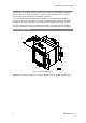
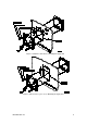
Figure 2 (ANSI 4" round cutout): Mounting the display unit Figure 3 (DIN 92x92mm square cutout): Mounting the display unit BG0456 REV.
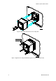
PM175 Quick Start Guide Figure 4: Slide and position the meter on locating studs Figure 5: Affix the meter using the thumb nuts (please do not over-tighten the nuts) 4 BG0456 REV.
PM175 Quick Start Guide Electrical Installation IMPORTANT! Only qualified personnel can perform setup. All incoming power sources must be turned off during installation. During operation of the Powermeter, hazardous voltages are present on the input terminals. Failure to observe precautions can result in serious or even fatal injury, or damage to equipment. Refer to the installation and operation manual for further information.
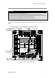
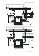
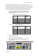
PM175 Quick Start Guide The diagrams below show typical installations of the PM175. Figure 7: Typical Installation 2 The typical installation diagram above shows a 4-Wire Wye 3-element connection using 3 PTs and 3 CTs. The wiring mode is 4LL3 or 4Ln3. Figure 8: Typical Installation 2 6 BG0456 REV.
PM175 Quick Start Guide The typical installation diagram above shows a 4-Wire Wye 2½-element connection using 2 PTs and 3 CTs. The wiring mode is 3LL3 or 3Ln3. The voltages must be balanced for the configuration to provide accurate power measurements. There are approximately nine different wiring configurations in the PM17X Series. Refer to the Installation and Operational Manual for additional configurations. For electrical installation of the display panel follow the following steps: 1.
PM175 Quick Start Guide Figure 9: PM175 Navigation buttons Setup is performed directly from the display panel or via the communication ports using PAS communication software. In Data Display mode, the navigation buttons function as follows. The MIN/MAX button switches to the Min/Max Maximum Demands display pages. When briefly pressed again, it switches back to the common measurements display.
PM175 Quick Start Guide Basic Setup Entering the Password The setup change menu is secured by a four-digit user password. The meter is primarily shipped with the password preset to 0, and password protection disabled. You can change the password and enable password protection through the Access Control menu. If authorization is not required, just press the ENTER button to move to the Main menu; otherwise enter a correct password to be authorized to access the meter setup.
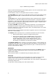
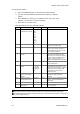
PM175 Quick Start Guide To change the option: 1. Press the SELECT button to activate the lower window. 2. Use the UP and DOWN arrow buttons to select the desired option. 3. Press ENTER to confirm your changes and to store your new setting, or press ESC to discard changes. 4. Press ESC to exit the menu. The table below lists the available options.
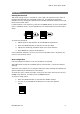
PM175 Quick Start Guide Setting the Communications You communicate with the meter via a changeable COM1 communication port, or through a second factory set serial RS-485/RS-422 COM2 port. Depending on what was ordered, the COM1 port is equipped with an RS-232/RS-422/RS-485 serial interface, with a dial-up modem for communicating through public telephone lines, or with an Ethernet module for communicating through the Internet. To configure the PM175 communication via PAS: 1.
PM175 Quick Start Guide AC0140 05-12001-3 Figure 10 COM1: Telephone Line Connection AC0139 RJ45 05-12001-4 Figure 11 COM1: Ethernet Connection 12 BG0456 REV.
PM175 Quick Start Guide Communicating via the Internet If you are communicating through the Ethernet port, define the IP address of your meter on the network. To define the IP address: 1. On the Instrument Setup tab, select Internet Site. 2. Click on the Connection tab. 3. Select the IP Address and type in the IP address of your meter. The default IP address preset at the factory is 192.168.0.203. 4. In the Protocol box, select the communications protocol for the TCP port.