PTS175 POLE TOP SENSOR MV ANALYZER Installation and Operation Manual BG0537 REV.
LIMITED WARRANTY The manufacturer offers the customer a 24-month functional warranty on the instrument for faulty workmanship or parts from date of dispatch from the distributor. In all cases, this warranty is valid for 36 months from the date of production. This warranty is on a return to factory basis. The manufacturer does not accept liability for any damage caused by instrument malfunction.
Table of Contents Chapter 1 General Information ............................................................................ 4 Chapter 2 Installation ............................................................................................ 6 2.1 Site Requirements .......................................................................................................6 2.2 Package Contents........................................................................................................6 2.
Chapter 1 General I N F O R M A T I O N Chapter 1 General Information The LINDSEY MV Line Post Sensors (or also known as Pole Top Sensor – PTS) replace standard MV line insulators and incorporate a built-in CT and PT like. The PTS converts the high voltage and current to a small voltage signal instead of the normal 120 Volt and 5 Amp outputs of standard CTs and PTs.
Chapter 1 General I N F O R M A T I O N Each Pole Top Sensor set includes the manufacturer test report showing V & I gain linearity and phase shift results, this information must be applied to the PM175-LSY through the General Setup\Instrument Transformer Correction menu using PAS™. Refer to PM175 Installation and Operation Manual (BG0415 REV.
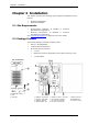
Chapter 2 Installation Chapter 2 Installation This chapter discusses the following types of physical installations for the PTS175: Mechanical Installation Electrical Installation 2.1 Site Requirements Environmental conditions: as specified in Specifications in Appendix A Technical Electrical requirements: as Specifications in Appendix A Technical specified in See Technical Specifications in Appendix A for more details 2.
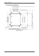
Chapter 2 Installation 2.3 Mechanical Installation Refer to the figures provided in this section to properly perform the mechanical installation.
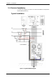
Chapter 2 Installation 2.4 Electrical Installation To setup and configure the PTS175 use PM175 Installation and Operation Manual (BG0415 REV.
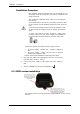
Chapter 2 Installation Installation Procedure Only qualified personnel familiar with the instrument and its associated electrical equipment must perform installation and setup procedures. The equipment installation shall conform to the following instructions: a) Circuits Breakers (AC and DC) in the PTS175 must be "OFF" b) HV Arresters must be installed closed to the PTS on the MV lines.
Chapter 3 Using P A S S O F T W A R E Chapter 3 Using PAS Software The support PAS software is a configuration and data acquisition tool that allows you to configure all of the PTS175/PM175 features, monitor your meters on-line, retrieve recorded files and view reports. Refer to PM175 Installation and Operation Manual (BG0415 REV.
Appendix A Technical Specifications Appendix A Technical Specifications PTS – Pole Top Sensor: A.1 Electrical Ratings: PTS MODEL Insulation Class Impulse AC withstand – 1mn Voltage Ratio Current Ratio Low Frequency dry flashover Low Frequency wet flashover A.2 A.3 9650/E1104 15kV 110kV 34kV 1400:1 600A:10V 80kV 60kV 9660/E1304 25kV 150kV 40kV 3300:1 600A:10V 110kV 85kV 9670/C14C0 35kV 200kV 50kV 10000:1 600A:10V 125kV 100kV PTS MODEL 9650/E1104 Insulation Class 15kV Cantilever strength (ultim.
Appendix A Technical Specifications Labels: Polycarbonate (UL94-V0) Ingress Protection: IP65 A.3 Power Supply inputs 120/230 VAC-DC Input: Rated input: 85-265VAC 50/60/400 Hz, 88-290VDC, Burden 9VA Lightening withstanding: 10,000A 12 VDC Input: Rated input: 12 VDC ± 10%, 10W Lightening withstanding: 1000A All Power supply sources must be grounded to earth A.4 Input Ratings Voltage Inputs Primary Measuring range: 11-33 KVAC line-to-line, 6.