
Instruction Manual


Chapter 2 Device Description
Controls and Indicators
12
PM180 Substation Automation Unit
Chapter 2 Device Description
Controls and Indicators
Device Controls
The PM180 is entirely controlled either from the remote display module (RDM or
RGM), or by using the supplemental PAS power analysis software package.
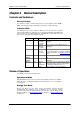
Indicator LEDs
The PM180 has three status indicator LEDs that show present device operation
status and give diagnostics indication; one energy pulsing LED that output kWh/kvarh
pulses, located on the attached Display; and COM port status LEDs that show
present ports status and communications activity.
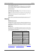
LED Name
Color
Status
Description
CPU
Green
Flashing
1 sec On,
1 sec Off
Device operational and is functioning
normally.
Flashing
2 flashes,
1 sec Off
Device is in the Service Mode and is not
operational.
Flashing
3 flashes,
1 sec Off
A critical error has occurred - the device is
not operational. Device servicing is required.
For more information, see Diagnostics Mode
below.
MAIN
POWER
Green
On
Voltage is supplied to the main power supply
unit.
BACKUP
POWER
Green
On
Voltage is delivered to the backup power
supply unit.
kWh/kvarh
Red
Flash at
user-
programme
d rate
The device measures imported (consumed)
active and reactive energy. For information
on defining the LED pulse rate, see
Advanced Device Setup in Chapter 7.
Modes of Operation
The PM180 can run in the following modes:
Operational Mode
Operational Mode is the common operation mode. All device features are available.
When the device is in Operational Mode the CPU LED flashes for 1 second with a 1-
second pause.
Energy Test Mode
Energy Test Mode tests the device energy measurement accuracy. All basic
measurements are available; energy accumulators are not affected; setpoints
operation, fault and power quality recorders are stopped. To put the device into the
Energy Test Mode, see Device Options Menu in Chapter 3, or Device Mode Control
in Chapter 11.