Quick Start Guide PM174 Powermeter BG0452 REV.
Introduction The PM174 is a compact, multi-function, three-phase AC Powermeter and Power Quality Analyzer specially designed to meet the requirements of users ranging from electrical panel builders to substation operators. If you are familiar with the PM174 Powermeter, use this quick start guide to prepare the unit for operation. If you are not familiar with the PM174, read the Installation and Operation Manual carefully before installing and using the unit.
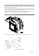
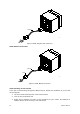
Figure 3: Slide and position the meter on locating studs Figure 4: Affix the meter using the thumb nuts (please do not over-tighten the nuts) BG0452 REV.
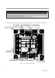
Electrical Installation IMPORTANT! Only qualified personnel can perform setup. All incoming power sources must be turned off during installation. During operation of the Powermeter, hazardous voltages are present on the input terminals. Failure to observe precautions can result in serious or even fatal injury or damage to equipment. Refer to the installation and operation manual for further information. The figure below shows all the connectors and terminals on the rear side of the PM174.
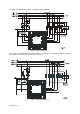
The diagrams below show typical installations of the PM174. Figure 6: Typical Installation 1 The typical installation diagram above shows a 4-Wire Wye 3-element connection using 3 PTs and 3 CTs. The wiring mode is 4LL3 or 4Ln3. Figure 7: Typical Installation 2 BG0452 REV.
The typical installation diagram above shows a 4-Wire Wye 2½-element connection using 2 PTs and 3 CTs. The wiring mode is 3LL3 or 3Ln3. The voltages must be balanced for the configuration to provide accurate power measurements. There are approximately nine different wiring configurations in the PM17X Series. Refer to the Installation and Operational Manual for additional configurations. For electrical installation of the display panel follow the following steps: 1.
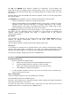
The UP and DOWN arrow buttons, labeled by arrowheads, scroll forwards and backwards through the display pages. Pressed briefly, they move one page forward or backward. If you hold the button down, the display pages are scrolled at rate of a twice per second. Pressing both the UP and DOWN arrow buttons together returns to the first page within the current display. The SELECT button operates once it’s released. The button has two functions: • When pressed briefly, switches to programming mode.
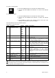
To select a setup option: bASc 1. Press the SELECT button to activate the middle window. ConF 2. Use the UP and DOWN arrow buttons to scroll to the desired option. 4Ln3 To change the option: 1. Press the SELECT button to activate the lower window. 2. Use the UP and DOWN arrow buttons to select the desired option. 3. Press ENTER to confirm your changes and to store your new setting, or press ESC to discard changes. The table below lists the available options. Press ESC to exit the menu.
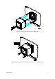
Setting the Communications You communicate with the meter via a changeable COM1 communication port, or through a second factory set serial RS-485/RS-422 COM2 port. Depending on what was ordered, your meter’s COM1 port can be equipped with an RS-232/RS-422/RS-485 serial interface, with a dial-up modem for communicating through public telephone lines, with an Ethernet module for communicating through the Internet, or with Profibus DP. To configure your communications with the PM174 from PAS software: 1.
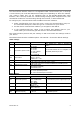
AC0140 05-12001-3 Figure 8 COM1: Telephone Line Connection COM1 Ethernet Connection AC0139 RJ45 05-12001-4 Figure 9 COM1: Ethernet Connection Communicating via the Internet If you are communicating through the Ethernet port, define the IP address of your meter on the network. 1. On the Instrument Setup tab, select Internet Site. 2. Click on the Connection tab. 3. Select the IP Address and type in the IP address of your meter. The default IP address preset at the factory is 192.168.0.203.
4. In the Protocol box, select the communications protocol for the TCP port. The meter can provide MODBUS/TCP connections on TCP port 502 and DNP3/TCP connections on port 20000. The host port is set automatically as you select the protocol. Select MODBUS RTU for MODBUS/TCP or DNP3 for DNP3/TCP. 5. In the Wait for Answer box, adjust the time that PAS waits for a connection before announcing an error and the number of retries PAS uses to receive a response from the device if communications fail.