
Owner's manual

Chapter 4 PAS
Application Software
Configuring Recorders
Series PM174 Powermeters 97
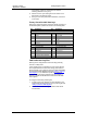
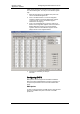
Event
ID
IEEE 1159 category Trigger parameter Reference
value
Typical
thresholds, %
Event
duration
PQE212 Instantaneous swell ½ cycle RMS voltage Un RMS 110-120% < 30 cycles
PQE221 Momentary interruption ½ cycle RMS voltage Un RMS 0-10% < 3 sec
PQE222 Momentary sag ½ cycle RMS voltage Un RMS 80-90% < 3 sec
PQE223 Momentary swell ½ cycle RMS voltage Un RMS 110-120% < 3 sec
PQE231 Temporary interruption ½ cycle RMS voltage Un RMS 0-10% < 1 min
PQE232 Temporary sag ½ cycle RMS voltage Un RMS 80-90% < 1 min
PQE233 Temporary swell ½ cycle RMS voltage Un RMS 110-120% < 1 min
PQE31 Sustained interruption ½ cycle RMS voltage Un RMS 0-10% > 1 min
PQE32 Undervoltage ½ cycle RMS voltage Un RMS 80-90% > 1 min
PQE33 Overvoltage ½ cycle RMS voltage Un RMS 110-120% > 1 min
PQE4 Voltage unbalance 3-sec negative
sequence unbalance
No 1-5% Steady state
PQE52 Harmonics THD 3-sec harmonic THD No 5-20% Steady state
PQE53 Interharmonics THD 3-sec interharmonic
THD
No 2-8% Steady state
PQE6 Voltage fluctuations
(flicker)
10-min Pst No 1-5 Steady state
PQE7 Frequency variations 3-sec frequency Nominal
frequency
1-6% Steady state
Un – nominal device voltage
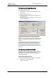
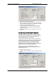
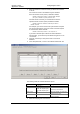
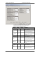
PQ Recorder Setup
The PQ recorder setup allows you to adjust thresholds and
hysteresis for PQ triggers, to define the waveform log options
for PQ events, and to enable or disable the PQ recorder in
your device.
To configure the PQ recorder:
1.
Select Memory/Log from the Meter
Setup menu, and then click on the PQ
Recorder tab.
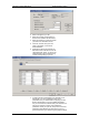
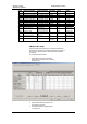
2.
Adjust thresholds and hysteresis for
PQ triggers if required.
3.
Select the waveform logging options
for PQ events.