
Owner's manual

Chapter 2 Installation Communications Connections
Series PM174 Powermeters 27
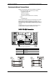
Communications Connections
Several communication options are available for the PM174:
COM1 (check the label on the back of your meter):
RS-232/RS-422/RS-485
56K Dial-up modem
Ethernet 10/100BaseT
Profibus DP (with firmware V24.2.1 and later)
COM2:
RS-422/RS-485
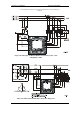
The RS-232/RS-422/RS-485 port is a standard port for COM1.
Other options are ordered separately. Connections to the
Ethernet RJ45 connector and to the telephone RJ11 connector
are made through a cable adaptor provided with your meter (if
ordered).
A full description of the communication protocols is found in
the PM174 protocol guides provided with your meter.
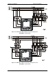
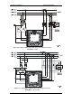
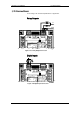
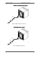
COM1 RS-232 Connection
0-1mA
0-20mA
V
-
+1mA
LOW DC
N
(24) 18-36VDC
(48) 36-72VDC
S
2
(12) 10-16VDC
+
7
3
9
6
5
1
-
4-20mA
9
8
COM.1 :
ATTENTION
Devices
Static-Sensitive
Static-Safe
Workstations
Handle Only at
POWER SUPPLY
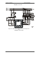
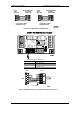
RS-422/RS-485
16
+RX
COM.2COM.1
11
V
1513 14
69
N
1
5
-TX +TX-RX
V
MODEM
PROFIBUS
ETHERNET
RS-232/422/485 STANDARD
3
17
12
L/+
N/-
10
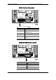
ANALOG IN/OUT :
Connector 9-pin D-type female:
Pin Signal
1 RS-232 RTS
2 RS-232 RxD
3 RS-232 TxD
4 RS-232 CTS
5 RS-232 Signal ground
PM174
RS -232
MALE CON.
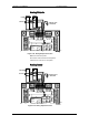
PM174
RS-232
MALE CON.