
Owner manual
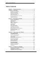

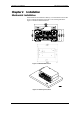
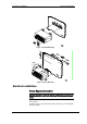
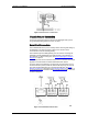
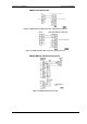
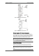
Table Of Contents
- General Information
- Installation
- Operating the ETC2002
- Connecting to the ETC2002
- Setting Up the ETC2002
- Changing the Password and Security
- Changing Time and Date
- Configuring Local Time Settings
- Configuring Serial Ports
- Configuring the Network
- Configuring Dial-Up Connections
- Configuring Wireless RF Connections
- Configuring Gateway Options
- Configuring Device Routing Table
- Configuring eXpertPower Client
- Configuring Data Server
- Upgrading Device Firmware
- Device Maintenance
- Technical Specifications
Chapter 2 Installation Electrical Installation
8 ETC2002 Network Communicator
Figure 2-5 Power Source Connection
Chassis Ground Connection
Connect the chassis ground of the device to the switchgear earth ground
using a dedicated wire greater than 2 mm
2
/14 AWG.
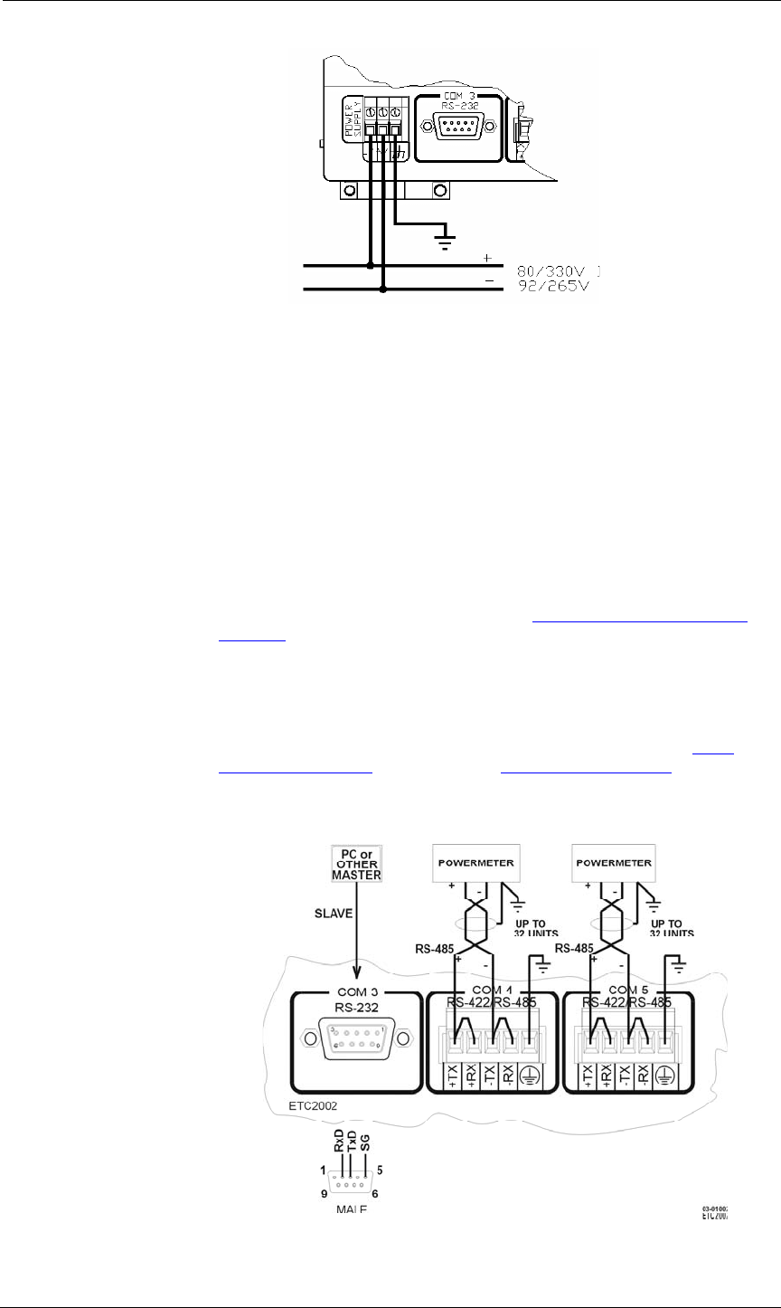
Serial Port Connection
The COM3 RS-232 service port is normally used for servicing and setting up
the ETC2002. It can also be used as a slave port for serial-to-serial
communications via the ETC2002 gateway.
The COM4 and optional COM5 gateway ports are used for connecting the
ETC2002 to the RS-422/RS-485 slave networks with up to 32 devices on
each network. For device routing rules, see Routing Messages over Slave
Networks in Chapter 3.
The COM4 port can also be used as a slave port for a connection of a master
application to the ETC2002 via an RS-422/RS-485 serial network.
For proper serial communications, ensure that all port parameters, such as
the communication protocol, baud rate, data format and parity, are correctly
set in both the ETC2002 and in the connected serial devices. See Serial
Network Connections in Chapter 3 and Configuring Serial Ports in Chapter 5
for the ETC2002 setup instructions. Refer to Figures 2-6 through 2-11 for the
connection diagrams.
Figure 2-6 Serial Network Connection