ETC2002 Network Communicator Installation and Operation Manual BG0328 Rev.
LIMITED WARRANTY The manufacturer offers the customer a 24-month functional warranty on the instrument for faulty workmanship or parts from date of dispatch from the distributor. In all cases, this warranty is valid for 36 months from the date of production. This warranty is on a return to factory basis. The manufacturer does not accept liability for any damage caused by instrument malfunction.
Chapter 1 General Information Table of Contents Chapter 1 General Information......................................................... 5 Chapter 2 Installation........................................................................ 6 Mechanical Installation ......................................................................... 6 Electrical Installation............................................................................. 7 Power Source Connection...............................................
Chapter 1 General Information Mechanical Installation Configuring Serial Ports ..................................................................... 34 Configuring the Network..................................................................... 35 Configuring Dial-Up Connections ...................................................... 37 Configuring Wireless RF Connections .............................................. 39 Configuring Gateway Options ..........................................................
Chapter 1 General Information Chapter 1 General Information The ETC2002 Network Communicator is a multi-port Internet-to-serial and Internet-to-wireless ZigBee gateway that connects multiple serial RS485/422 or wireless ZigBee devices to the Internet via a local Ethernet network or via public telephone lines. It can also be used as an Internet-toInternet router for connecting master stations to remote slave devices that are directly connected to the Internet.
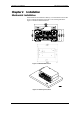
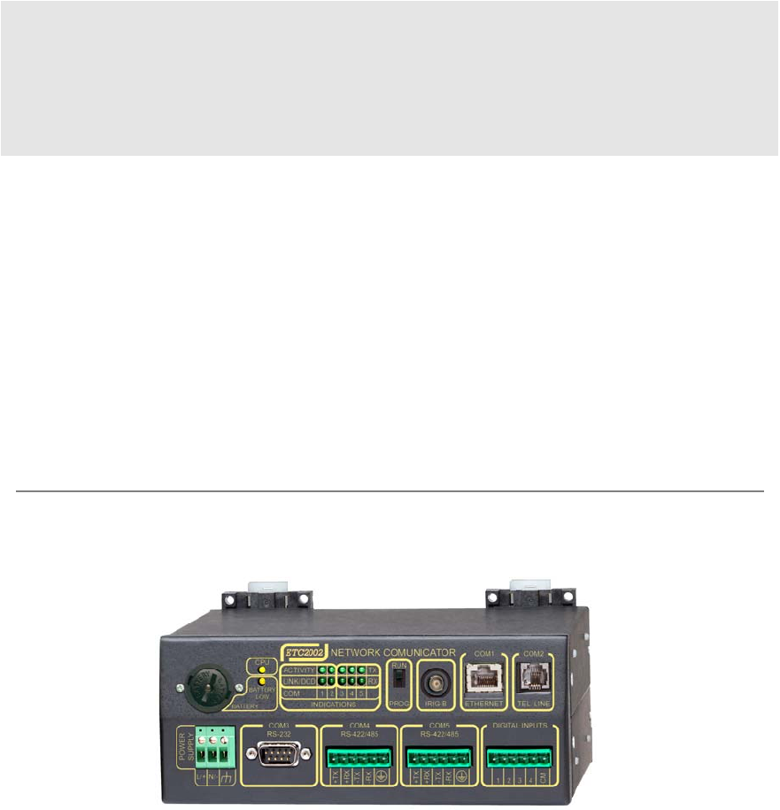
Chapter 2 Installation Mechanical Installation Chapter 2 Installation Mechanical Installation The ETC2002 can be located on a table top, or be mounted on a 35-mm DIN rail or on a panel. See Figures 2-2 through 2-4 for mounting instructions. Figure 2-1 shows the device dimensions. ETC2002 COM 1 POWER SUPPLY COM 3 RS-232 L/+ N/- 1 2 3 4 5 INDICATIONS COM 4 RS-422/485 +TX +RX -TX -RX LOW BATTERY TX RX COM 2 RUN IRIG-B COM 5 RS-422/485 TEL.
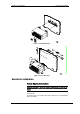
Chapter 2 Installation Electrical Installation Figure 2-3 Din Rail Mounting Figure 2-4 Panel Mounting Electrical Installation Power Source Connection Before connecting your device to the power source, check the label on the back of the device to ensure that it is equipped with the appropriate power supply. AC power supply: Connect the line wire to terminal L/+ and the neutral wire to terminal N/-. DC power supply: Connect the positive wire to terminal L/+ and the negative wire to terminal N/-.
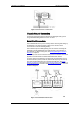
Chapter 2 Installation Electrical Installation Figure 2-5 Power Source Connection Chassis Ground Connection Connect the chassis ground of the device to the switchgear earth ground 2 using a dedicated wire greater than 2 mm /14 AWG. Serial Port Connection The COM3 RS-232 service port is normally used for servicing and setting up the ETC2002. It can also be used as a slave port for serial-to-serial communications via the ETC2002 gateway.
Chapter 2 Installation Electrical Installation COM3 RS-232 Connection Figure 2-7 Simple RS-232 3-Wire Connection, 9-pin Female Connector Figure 2-8 Simple RS-232 3-Wire Connection, 25-pin Connector COM4/COM5 RS-422/RS-485 Connection Figure 2-9 Multidrop RS-422 Connection ETC2002 Network Communicator 9
Chapter 2 Installation Electrical Installation Figure 2-10 Multidrop RS-485 Connection Figure 2-11 Multidrop RS-485 Connection Wireless ZigBee RF Modem Connection An external IP-Link 2000 modem is used for connecting the ETC2002 to a wireless ZigBee network. Connect the IP-Link 2000 RS-485 terminals A and B to the COM5 +TX and -TX terminals respectively. Make a short between COM5 terminals +TX and +RX, and between terminals –TX and –RX.
Chapter 2 Installation Electrical Installation Ethernet Connection Plug the end of the Ethernet cable that came with your device into the wall Ethernet jack or into the Ethernet hub jack, and the other end into the RJ45 jack at the front of the ETC2002 marked COM1/ETHERNET. Figure 2-12 Network Connections See Internet Connections in Chapter 3 and Configuring the Network in Chapter 5 for instructions on how to program your device for networking via Ethernet.
Chapter 3 Operating the ETC2002 Controls and Indicators Chapter 3 Operating the ETC2002 Controls and Indicators PROG-RUN Switch The ETC2002 has a PROG-RUN switch that puts the device into program mode for local servicing and programming. The switch must be in the RUN position for normal device operation. Put the PROG-RUN switch in the PROG position for setting up your device or upgrading device firmware via a Terminal program (see Using HyperTerminal in Chapter 4 for instructions).
Chapter 3 Operating the ETC2002 Modes of Operation Modes of Operation Operational Mode In the operational mode, the device services the Internet to serial gateway connections from client applications, and the COM3 port operates in slave mode allowing serial-to-serial network connections. To put the ETC2002 into operational mode, set the PROG-RUN switch in the RUN position.
Chapter 3 Operating the ETC2002 Using the ETC2002 A wireless network is used as a transparent media for delivering Modbus RTU messages. To identify devices on the network, each slave node is assigned a network ID that is identical to the device Modbus address. See Configuring Wireless RF Connections in Chapter 5 for information on configuring the IP-Link module parameters in the ETC2002. Internet Connections Starting with V21.5.
Chapter 3 Operating the ETC2002 Using the ETC2002 See Configuring Dial-Up Connections in Chapter 5 for more information on configuring your modem. See Dial-Up Networking in Chapter 4 for information on using Windows Dial-Up Networking for dial-in connections. Dial-Out Connections Dial-out connections are normally used with eXpertPowerTM applications. The ETC2002 eXpertPower client can initiate connections to the eXpertPowerTM server on a time basis.
Chapter 3 Operating the ETC2002 Using the ETC2002 The ETC2002 has two options for routing messages over the slave networks, depending on whether the device routing table is defined in your ETC2002 or not. The first option uses implicit rules that identify the device location statically upon the device address. The following table shows how the messages are routed through the COM4 and COM5 serial ports depending on the port usage.
Chapter 3 Operating the ETC2002 Using the ETC2002 ETC2002 Network Applications Transparent Gateway The ETC2002 normally provides a means for transparent exchange of messages between master Internet and serial client applications, and slave serial or wireless devices. The ETC2002 can manage up to eight concurrent sessions between master stations and slave devices. Each connection is fully transparent for the master.
Chapter 3 Operating the ETC2002 Using the ETC2002 updates from the ETC2002 clock, which may be synchronized with the precise satellite GPS clock using an optional IRIG-B input. Acquired real-time data is normally stored in the ETC2002 exchanges. If the user wishes, acquired data can be periodically moved to historical circular files where data is kept for a long time until it is overwritten by newer data. Data is recorded to historical files at regular intervals.
Chapter 3 Operating the ETC2002 Using the ETC2002 Monitoring Digital Inputs The Data server provides continuous monitoring events asserted by the ET2002 digital inputs and gives notification to the eXpertPower server. Whenever the Data server detects a change in the status of the ETC2002 digital inputs, it records an event record to the Event log file. If the eXpertPower service is enabled in the ETC2002, this event initiates a connection to the eXpertPower server.
Chapter 4 Connecting to the ETC2002 Using HyperTerminal Chapter 4 Connecting to the ETC2002 Using HyperTerminal Windows HyperTerminal allows you to configure the network, communications and security settings in your ETC2002, and to view certain diagnostic information such as device diagnostics and network statistics. HyperTerminal is also used for servicing the ETC2002 and upgrading the device firmware. Running HyperTerminal 1. 2. 3.
Chapter 4 Connecting to the ETC2002 6. Using HyperTerminal From the File menu, select Save to save your settings for the ETC2002 session. When you next open a session and the New Connection dialog appears, click Cancel, select Open from the File menu, and then double-click on your session file. Opening a Terminal Session Put the PROG-RUN key on the ETC2002 in the PROG position.
Chapter 4 Connecting to the ETC2002 stop dump stop net stop server reset quit Using Telnet Stops dumping the log to console Shuts the network down Shuts the TCP server down Resets the device Quit console You are prompted for the password to login, as in the following example: Login password: * > If your login was successful, you are not prompted for the password again until you close the terminal session. The default ETC2002 password is 0 unless you have changed it.
Chapter 4 Connecting to the ETC2002 Using Telnet Running the Telnet Client 1. From the Start menu, select Run, type telnet and click OK. The following text appears in a window: Microsoft (R) Windows 2000 (TM) Version 5.00 (Build 2195) Welcome to Microsoft Telnet Client Telnet Client Build 5.00.99206.1 Escape Character is 'CTRL+]' Microsoft Telnet> 2. Type open followed by the ETC2002 IP address, followed by 5023 as the ETC2002 port number, for example: Microsoft Telnet>open 192.168.0.
Chapter 4 Connecting to the ETC2002 mbus ID modem XP time [hh:mm:ss] date [dd/mm/yy] log stat stat ip stat xp service datasrv run dump run server stop dump stop server reset rsttmr quit Dial-Up Networking - Set MODBUS ID range and ETC MODBUS - Modem connection parameters eXpertPower client parameters Time Date Prints network log Prints network statistics Prints current network IP addresses Prints XP client status Service Menu Data server configuration Starts dumping the log to console Starts the TCP ser
Chapter 4 Connecting to the ETC2002 Dial-Up Networking 3. Select “I want to set my Internet connection manually” and click Next. 4. Select “I connect through a phone line and a modem” and click Next. 5. Select a modem you use to connect to the Internet and click Next.
Chapter 4 Connecting to the ETC2002 26 Dial-Up Networking 6. Type the telephone number of the ETC2002 modem and click Next. 7. Leave the user name and password boxes blank and click Next. In dialin mode, the ETC2002 does not require the name and password to login.
Chapter 4 Connecting to the ETC2002 8. Type the connection name and click Next. 9. Check “No” and click Next. Using PAS Software Later, you can use the name of your Dial-up connection in Internet applications to dial to the ETC2002. For all Dial-up Internet connections, use the IP address you have defined in your ETC2002 for the modem interface via the Dial-Up Networking Setup (see Configuring Dial-Up Connections in Chapter 5).
Chapter 4 Connecting to the ETC2002 Using PAS Software database so that PAS recognizes device properties regardless of whether the ETC2002 is online or offline. To create a new database for your ETC2002: 1. Select Configuration from the Tools menu, and then click the Sites button on the right-hand side. 2. From the “Look in” box, select the directory where the new database will be stored. By default, it is the “Sites” directory.
Chapter 4 Connecting to the ETC2002 Using PAS Software Communicating through a Dial-up Connection Configuring a Dial-up Connection To communicate through a Dial-up modem: 1. 2. On the Instrument Setup tab, select Internet Site. Click on the Connection tab. 3. Click on the “IP address” and type in the IP address you defined in Dial-Up Networking Setup in your ETC2002. The default IP address preset at the factory is 192.168.10.203.
Chapter 4 Connecting to the ETC2002 6. 7. Using PAS Software In the “Connection” box, select the Dial-up connection you created for the ETC2002. See Dial-Up Networking for information on how to create a Dial-up connection in Windows. Check the AutoDial box, if you wish PAS to automatically connect to your ETC2002 every time you access it from PAS; otherwise you must manually dial your connection. Manually Dialing your Connection To manually dial your connection: 1.
Chapter 4 Connecting to the ETC2002 Using PAS Software Uploading Setup from the ETC2002 To upload the setup from the ETC2002 to the site database, check the Online button on the PAS toolbar, select the device site from the list box on the toolbar, and then select Upload Setups from the Meter Setup menu. Authorization If communications with your ETC2002 is secured, you are prompted for the password when you send new setup data to the device. Enter the password and click OK.
Chapter 5 Setting Up the ETC2002 Changing the Password and Security Chapter 5 Setting Up the ETC2002 You can configure your ETC2002 via the Terminal program connected to the device through the COM3 service port, via the Telnet, or via PAS. See Connecting to the ETC2002 for information on establishing a connection with your device using different communication options. Changing the Password and Security Using HyperTerminal or Telnet To change your password or a security option: 1.
Chapter 5 Setting Up the ETC2002 Changing Time and Date Changing Time and Date Using HyperTerminal or Telnet To view or change time or date in the ETC2002, type time or date, and then press Enter. To change the time or date, type the new setting after the prompt and press Enter. To leave the time unchanged, just press Enter.
Chapter 5 Setting Up the ETC2002 Parameter DST end month DST end week DST end weekday Configuring Serial Ports Options Default Month-weekLast weekday Sunday in Week = 1st, 2nd, 3rd, October 4thor Last (last week of the month) Description The date when Daylight Savings Time ends. The DST switch point is specified by the month, week of the month and weekday. By default, DST ends at 2:00 AM on the last Sunday in October of each year. The daylight savings time option is disabled in the ETC2002 by default.
Chapter 5 Setting Up the ETC2002 Configuring the Network Using PAS To enter the setup dialog, select the ETC2002 site from the list box on the PAS toolbar, select Communications Setup from the Meter Setup menu, and then click on the Serial Ports Setup tab. Select the desired device port in the “Port” box. To change the port settings, select desired port parameters, and then click Send. See Serial Port Connection in Chapter 3 for information on using serial ports and available options.
Chapter 5 Setting Up the ETC2002 Configuring the Network New: Network subnet mask: 255.255.255.0 New: Network default gateway: 192.168.0.1 New: Refer to your network administrator for the available IP address and correct subnet mask and default gateway settings. If you enable DHCP (Dynamic Host Configuration Protocol), the ETC2002 obtains the network settings automatically from your network server when the ETC2002 restarts.
Chapter 5 Setting Up the ETC2002 Configuring Dial-Up Connections The following table lists available network options. Parameter Device IP Address Network Subnet Mask Network Default Gateway TCP Service Port Options 502 = Modbus/TCP 20000 = DNP3/TCP 5002 = SATEC ASCII/TCP Default 192.168.0.203 255.255.255.0 192.168.0.1 502 NOTE: Starting with V21.5.4, the ETC2002 provides the permanent Modbus/TCP server on port 502.
Chapter 5 Setting Up the ETC2002 , W Configuring Dial-Up Connections Dial pause: the modem will pause for a specified time before dialing the following digits. Wait for dial tone: the modem will wait for a dial tone before dialing the digits following "W". @ Wait for silence: the modem will wait for at least 5 seconds of silence before continuing with the next dial string parameter. () Ignored: may be used to format the dial string. Ignored: may be used to format the dial string.
Chapter 5 Setting Up the ETC2002 Parameter Configuring Wireless RF Connections Options Default Description Dial-out Connection Options Redial Attempts 0-1000, 0 0 = dial forever The number of dial attempts to connect to a remote modem if a connection was unsuccessful. Time Between Redial Attempts 0-9999 sec 1 A time delay between redials. Connection Timeout 0-9999 sec 180 The modem cancels a call if not connected within the connection timeout time.
Chapter 5 Setting Up the ETC2002 Configuring Wireless RF Connections New: Refer to the table below for the available RF modem options. NOTES: 1. 2. Do not change the default zero MAC Node ID. Set the RF channel frequency and the MAC Network ID in all remote nodes the same as you selected in the ETC2002. RF Network Options To view or change the RF network parameters, type net and press Enter. If you want to change a parameter, type your new setting after the prompt and press Enter.
Chapter 5 Setting Up the ETC2002 Configuring Gateway Options The following table lists available RF modem options.
Chapter 5 Setting Up the ETC2002 Configuring Gateway Options New: End address: 215 New: Sharing control Enabled [y/n]: N New [y/n]: > See Routing Messages over Slave Networks in Chapter 3 for information on defining the gateway address range and the ETC2002 service address. See Shared Device Access in Chapter 3 for information on shared device accesses.
Chapter 5 Setting Up the ETC2002 Configuring Device Routing Table Configuring Device Routing Table Using PAS To enter the Setup dialog, select the ETC2002 site from the list box on the PAS toolbar, select ETC2002 Setup from the Meter Setup menu, and then click on the Device Routing Table tab. The routing table allows you to specify a routing path and the shared device access rules for every slave device connected to the ETC2002. Note that the Ethernet devices can only be accessed via the routing table.
Chapter 5 Setting Up the ETC2002 Configuring eXpertPower Client NOTE: Enable the routing table via the ETC2002 Gateway Options Setup to make it effective in your ETC2002 (see Configuring Gateway Options above). Configuring eXpertPower Client Using HyperTerminal or Telnet To view or change the eXpertPowerTM settings, type xp and press Enter. To change a parameter, type your new setting after the prompt and press Enter. To leave the setting unchanged, just press Enter. >xp XpertPower IP address: 194.90.
Chapter 5 Setting Up the ETC2002 Configuring Data Server The following table lists available options. Parameter Options XPW Server IP Address Default Description 207.232.60.
Chapter 5 Setting Up the ETC2002 Configuring Data Server Data Server Options To view the Data server options, type i and press Enter. Data server>i Data Server Configuration -----------------------------------Data server disabled Continuous polling disabled Polling interval 1 min Logging interval 1 (x1min) To setup or change the Data server options, type p and press Enter. To change an option, type your new setting after the prompt and press Enter. To leave the setting unchanged, just press Enter.
Chapter 5 Setting Up the ETC2002 5. Configuring Data Server Specify the start device register and the number of registers in the write data exchange: Write block start register address: 200 New: Number of registers: 10 New: 6. Enable polling for the write data exchange if you want to start exchange operations: Polling: disabled New [y/n]: 7. Specify the device status register and a register mask for a status event exchange: Status register address: 400 New: Status register mask: 0xC000(HEX) New: 8.
Chapter 5 Setting Up the ETC2002 Configuring Data Server The following table lists available Data server options.
Chapter 5 Setting Up the ETC2002 Configuring Data Server See Data Server in Chapter 3 for more information on using real-time data exchanges. Refer to the ETC2002 Modbus Guide for information on how to access the acquired real-time and logged data via communications. The following table lists available options.
Chapter 5 Setting Up the ETC2002 Configuring Data Server Status Event Exchanges To enter the Setup dialog, select the ETC2002 site from the list box on the PAS toolbar, select ETC2002 Setup from the Meter Setup menu, and then click on the Status Event Exchanges tab. See Data Server in Chapter 3 for more information on using status event exchanges. Refer to the ETC2002 Modbus Guide for information on how to access the event log data via communications. The following table lists available options.
Chapter 5 Setting Up the ETC2002 5. Configuring Data Server Check the “Auto Reset” box if you want the status register to be cleared after polling. Write Data Exchanges To enter the Setup dialog, select the ETC2002 site from the list box on the PAS toolbar, select ETC2002 Setup from the Meter Setup menu, and then click on the Write Data Exchanges tab. See Data Server in Chapter 3 for more information on using data exchanges.
Chapter 6 Upgrading Device Firmware Chapter 6 Upgrading Device Firmware This chapter describes the procedure of upgrading firmware in the ETC2002 through the COM3 RS-232 service port using Windows HyperTerminal. When you put your device into program mode, its COM3 port operates at 19200 baud by default. Downloading firmware at a slow baud rate may be very time-consuming. It is recommended to use the maximum available speed of 115200 baud for downloading firmware.
Chapter 6 Upgrading Device Firmware Baud Rate: 19200 New: 115200 5. 6. 7. Print 115200 and press Enter. Now the Flash Loader communicates at 115200 baud. To accommodate HyperTerminal to the new baud rate, select Open from the File menu, click Yes in response to the HyperTerminal question, and then double-click on your “115200” session file. Print p and press Enter. The following text appears: p Programming Flash ----------------Send HEX-32 file as a text file. NB: Use standard XON/XOFF flow control.
Chapter 7 Device Maintenance Chapter 7 Device Maintenance This chapter describes the battery replacement procedure. See Figures 7-1 to 7-4 for replacement instructions. Ì Observe the battery polarity. The battery polarity appears on the inner part of the battery cover.
Chapter 7 Device Maintenance Figure 7-3 Battery Removal Figure 7-4 Insertion of New Battery ETC2002 Network Communicator 55
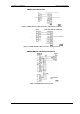
Appendix Technical Specifications Appendix Technical Specifications Environmental Conditions Operating temperature: -20°C to 60°C (-4°F to 140°F) Storage temperature: -25°C to 80°C (-13°F to 176°F) Humidity: 0 to 95% non-condensing Construction Dimensions: see Figure 2-1 Weight: 1.23kg (2.7 lb.) Materials Enclosure: Aluminum Terminals: PBT (UL94-V0) Connectors: plug-in type, Polyamide PA6.
Appendix Technical Specifications Connector type: DB9 female Baud rate: up to 115.2 kbps Supported protocols: Modbus RTU, Modbus ASCII and DNP3 COM4, COM5 RS-422/RS-485 optically isolated ports Isolation: 2,000 V RMS Connector type: removable, 5 pins 2 Wire size: up to 12 AWG (up to 2.5 mm ) Terminals pitch: 5 mm Baud rate: up to 115.