
Installation Manual Owner's manual

Appendix: Technical Specifications
30
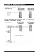
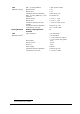
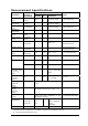
Measurement Specifications
Accuracy
Parameter Full Scale @
Input Range
%
Reading
%
FS
Conditions
Range
Voltage V1-V3
(L-n)
120 x PT ratio
@ 120V
0.05
±0.0
5
1% up to 140% 0 up to 999,000 V
Voltage V4
(calculated)
120V x PT ratio
@ 120V
±0.5
5% up to 140%
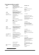
Voltage V1-V3
(L-n)
69 x PT ratio 0.1
±0.0
5
1% up to 140% 0 up to 999,000 V
Voltage V4
(calculated)
69 x PT ratio ±0.5
5% up to 140%
Line current
I1- I4
CT primary
current
±0.06 ±0.0
6
1% up to 120% In 0 up to 20,000 A
Fault current
I1- I4
CT primary
current
±0.5 - 120%- 1000% In 0 up to 100,000 A
Active power
3xV
FS×CT/1000
0.2 0.02
|PF| ≥ 0.5
*
-10,000,000 kW to
+10,000,000 kW
Reactive power
3xV
FS×CT/1000
0.3 0.04
|PF| ≤ 0.9
*
-10,000,000 kvar to
+10,000,000 kvar
Apparent
power
3xV
FS×CT/1000
0.2 0.02
|PF| ≥ 0.5
*
0 to 10,000,000 kVA
Power factor
1.000 0.2 |PF| 0.5, I 2
%
FSI
-0.999 to +1.000
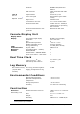
50 Hz - ±0.0
2
40-65 Hz 40.00 up to 64.99 Hz
Frequency
60 Hz - ±0.0
2
45- 70 Hz 45.00 up to 69.99 Hz
Total Harmonic
Distortion, THD
V
(I), %V
f
(%I
f
)
999.9 1.5 0.1
THD ≥ 1%,
V
(I) ≥ 10% FSV
(FSI)
0 to 999.9
Total Demand
Distortion,
TDD, %
100 1.5
TDD ≥ 1%,
I ≥ 10% FSI
0 to 100
Active energy
Import &
Export
ANSI C12.20, Class 10/20, Acc. Class
0.2S
0 to 999,999.999 MWh
Reactive
energy
Import &
Export
Class 0.5S under conditions as per
IEC 62053-22:2003 @ 0≤ |PF| ≤ 0.9
0 to 999,999.999 Mvarh
Apparent
energy
Class 0.2S under conditions as per
IEC 62053-22:2003
0 to 999,999.999 MVAh
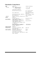
Symmetrical
components
Voltage FS
Current FS
Current FS
1.0
1.0
3.0
10% - 120% FS
10% - 200% FS
200% -
3000%FS
Phasor angles 1 degree
*
@ 80% to 120% of voltage FS, 2% to 200% of current FS, and frequency 50/60 Hz
PT - external potential transformer ratio