
User Manual
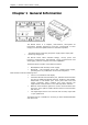

Chapter 1 General I N F O R M A T I O N
EM13x Series SMART MULTIFUNCTION METER 7
Table of Contents
Chapter 1 General Information .......................................................................... 10
1.1 Features .......................................................................................................................11
1.2 Available Options .......................................................................................................12
Digital I/O ............................................................................................................ 12
Analog Output ...................................................................................................... 13
Additional Communication Port – COM2 ................................................................... 13
1.3 Customized Options ..................................................................................................13
Device Resolution .................................................................................................. 13
Display Options ..................................................................................................... 13
1.4 Measured Parameters ..............................................................................................13
Chapter 2 Installation .......................................................................................... 16
2.1 Site Requirements .....................................................................................................16
2.2 Package Contents ......................................................................................................16
2.3 Mechanical Installation .............................................................................................16
Wall Mounting ....................................................................................................... 18
DIN Rail Mounting ................................................................................................. 19
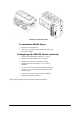
Add-On Module Mounting ....................................................................................... 20
2.4 Electrical Installation .................................................................................................21
Typical Installation ................................................................................................ 21
Terminals ............................................................................................................. 23
Power Source Connection ....................................................................................... 23
Voltage Input connection ....................................................................................... 24
Current Input Connection ....................................................................................... 25
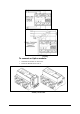
Wiring Diagrams ................................................................................................... 26
2.5 Battery Replacement ................................................................................................31
2.6 I/O Connections ........................................................................................................32
2DI/1RO Standard ................................................................................................ 32
4DI/2RO Module ................................................................................................... 33
12DI/4RO Module ................................................................................................. 34
4AO Module - Analog Outputs ................................................................................. 35
2.7 Communications Connections .................................................................................37
COM1 RS-485 Connection ...................................................................................... 38
ETH module – COM2 Ethernet Connection................................................................ 39
PRO module – COM2 PROFIBUS Connection ............................................................. 40
RS-232/422-485 module – COM2 Connection .......................................................... 41
Connecting a GSM/GPRS module ............................................................................ 42
Connecting an RF module ...................................................................................... 42
Chapter 3 Using Front Display ............................................................................ 43
Energy Pulse LED .................................................................................................. 43
COM Port Activity LEDs .......................................................................................... 43
VOLTAGES LEDs ................................................................................................... 43
Navigation Buttons ................................................................................................ 43
3.1 Display Operations ....................................................................................................44
Navigation Buttons ................................................................................................ 44
Navigating in Data Display Mode ............................................................................. 45
Display Features ................................................................................................... 45
Measurement Units ............................................................................................... 46
3.2 Data Displays ..............................................................................................................46