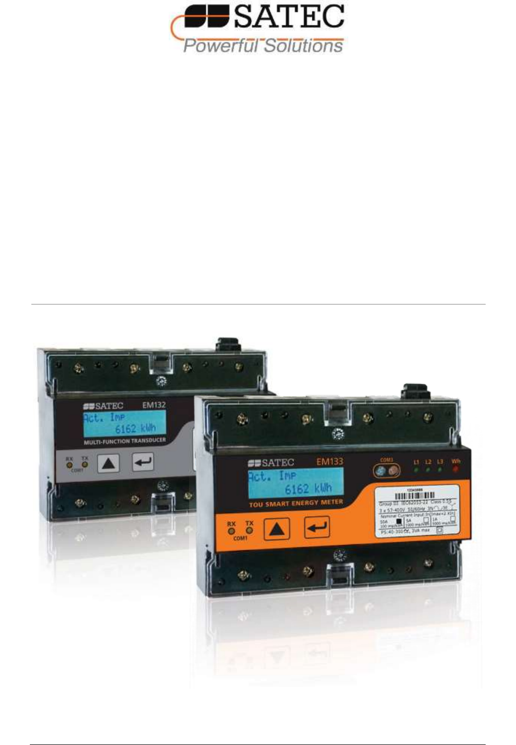
EM13x Series SMART MULTIFUNCTION METER Installation and Operation Manual BG0491 REV.
LIMITED WARRANTY The manufacturer offers the customer a 24-month functional warranty on the instrument for faulty workmanship or parts from date of dispatch from the distributor. In all cases, this warranty is valid for 36 months from the date of production. This warranty is on a return to factory basis. The manufacturer does not accept liability for any damage caused by instrument malfunction.
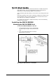
Quick Start Guide This section can be used by a licensed electrician to install and perform basic EM13X setup. For more detailed EM13X Series setup and use instructions, see the following chapters in this manual. This quick start guide will assist you to have the unit running for the first time. During the operation of the meter, hazardous voltages are present in the input terminals. Failure to observe precautions can result in serious or even fatal injury or damage to equipment.
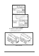
To mount the EM13X Series on flat surface: Locate the EM13X Series on the surface to Push up the DIN rail brackets to lock the EM13X Series on the rail. Connecting the EM13X Series Unit Ensure that all incoming power sources are OFF. Check that you have the appropriate power supply. For direct connection, connect to CT wires through the meter CT terminals. Observe the arrow that indicates the current direction.
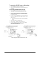
CT wiring To connect an Option module: Assemble the module on the meter. Power the EM13X Series unit on.
Assembling the 12DI/4RO module To operate the EM13X Series: Perform device diagnostics. Configure the device through the EM13X Series unit front panel display. Configuring the EM13X Series remotely Install the PAS application software on your PC. Configure the PAS database for your meter. Configure the PAS communications settings. Upgrade the meter firmware if a new version is available. Set up the meter using the PAS application software.
Chapter 1 General I N F O R M A T I O N Table of Contents Chapter 1 General Information ..........................................................................10 1.1 Features.......................................................................................................................11 1.2 Available Options .......................................................................................................12 Digital I/O ....................................................................
Chapter 1 General I N F O R M A T I O N TEST Mode Data Display ........................................................................................ 46 Billing Period Energy Data Displays ......................................................................... 46 TOU/Maximum Demand Power Data Display ............................................................ 48 Instrumentation Measurement Maximum Demand Data Display ................................. 50 Instrumentation Measurement...................
Chapter 1 General I N F O R M A T I O N Chapter 7 7.1 7.2 7.3 7.4 Monitoring Meters........................................................................... 106 Viewing Real-time Data......................................................................................... 106 Viewing Real-time Min/Max Log ......................................................................... 109 Viewing Real-time Waveforms ............................................................................
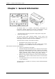
Chapter 1 General I N F O R M A T I O N Chapter 1 General Information The EM13X Series is a compact, multi-function, three-phase AC Powermeter specially designed to meet the requirements of users ranging from electrical panel builders to substation operators.
Chapter 1 General I N F O R M A T I O N 1.1 Features Multifunctional 3-phase Power Meter 3 voltage inputs and 3 current transformer-isolated AC inputs for direct connection to power line or via potential and current transformers True RMS, volts, amps, power, power factor, neutral current, voltage and current unbalance, frequency Ampere/Volt demand meter 25/50/60/400 Hz measurement capabilities Billing/TOU Energy Meter Class 0.
Chapter 1 General I N F O R M A T I O N Display Easy to read 2x16 characters LCD display, adjustable update time Auto-scroll option with adjustable page exposition time; autoreturn to a default page Communications Standard 2-wire RS-485 communication port; MODBUS RTU, DNP3, SATEC ASCII and IEC 60870-5-101 communication protocols Optional second communication port; MODBUS RTU, MODBUS/TCP, DNP3, DNP3/TCP, SATEC ASCII, PROFIBUS DP and IEC 60870-5-104 (over TCP) communication protocols eXp
Chapter 1 General I N F O R M A T I O N and pulse operations, failsafe operation for alarm notifications; programmable pulse width; direct remote relay control through communications; 1-cycle update time. 12DI/4RO Module 12 dry contact digital inputs (DI) for monitoring external contacts and receiving pulses from energy, water, and gas meters; Programmable de-bounce time; 1-ms scan time.
Chapter 1 General I N F O R M A T I O N Parameter kW per phase Display Comm.
Chapter 1 General I N F O R M A T I O N Parameter Total kVAh Display Comm.
Chapter 2 Installation Chapter 2 Installation This chapter discusses the following types of physical installations for the EM13X Series SMART MULTIFUNCTION METER: Mechanical Installation Electrical Installation I/O Connections COM Port Connections. 2.
Chapter 2 Installation Figure 2-1 Dimensions EM13x Series SMART MULTIFUNCTION METER 17
Chapter 2 Installation Wall Mounting To mount the meter on the wall: Position the meter on the wall according to hole locations as shown in figure 2-2 Affix the meter using washers and nuts. Figure 2-2.
Chapter 2 Installation DIN Rail Mounting The EM13X Series can be mounted on a standard 35-mm DIN rail as shown in figure 2-3 Figure 2-3.
Chapter 2 Installation Add-On Module Mounting Before Add-On Module installation ensure that all incoming power sources are shut OFF. Failure to observe this practice can result in serious or even fatal injury and damage to equipment. Turn off the EM13X Series auxiliary power supply or voltage supply inputs (SE model). Remove the module connector cover from the EM13X Series to access the module connector as shown in figure 2-4below Figure 2-4. EM13X Series module connector location Figure 2-5.
Chapter 2 Installation 2.4 Electrical Installation The equipment installation shall conform to the following instructions: a) a switch or circuit-breaker shall be included in the building installation; b) It shall be in close proximity to the equipment and within easy reach of the OPERATOR; c) It shall be marked as the disconnecting device for the equipment. Before installing, ensure that all incoming power sources are shut OFF.
Chapter 2 Installation Figure 2-7b Typical Installation Diagram with Self Energized Power Supply 22 EM13x Series SMART MULTIFUNCTION METER
Chapter 2 Installation Terminals Figure 2-8 Terminals View Power Source Connection The equipment installation shall conform to the following instructions: a) a switch or circuit-breaker shall be included in the building installation; b) It shall be in close proximity to the equipment and within easy reach of the OPERATOR; c) It shall be marked as the disconnecting device for the equipment. Before installing, ensure that all incoming power sources are shut OFF.
Chapter 2 Installation Figure 2-9 EM13X Series Auxiliary Power Supply connection Voltage Input connection The equipment installation shall conform to the following instructions: a) a switch or circuit-breaker shall be included in the building installation; b) It shall be in close proximity to the equipment and within easy reach of the OPERATOR; c) It shall be marked as the disconnecting device for the equipment. Before installing, ensure that all incoming power sources are shut OFF.
Chapter 2 Installation EM13X-SE model Voltage connections Figure 2-11b EM13X-SE model measured Voltage connections EM133-SE model with measuring nominal current 1A or 5A or 20mA (using HACS), indirect connection – nominal voltage input is up to 277(480) VAC. EM133-SE model with measuring nominal current 50A, connection – nominal voltage input is up to 230(400) VAC.
Chapter 2 Installation Wiring Diagrams For AC input ratings, see Technical Specifications in Appendix A for more details. Table 2 presents the available wiring configurations in the meter.
Chapter 2 Installation Figure 2-14 4-Wire Wye 3-Element Direct Connection Using 3 CTs (Wiring Mode = 4LL3 or 4Ln3) Figure 2-15 4-Wire Wye 3-Element Connection Using 3 PTs, 3 CTs (Wiring Mode = 4LL3 or 4Ln3) EM13x Series SMART MULTIFUNCTION METER 27
Chapter 2 Installation Figure 2-16 3-Wire 2-Element Open Delta Connection Using 2 PTs, 2 CTs (Wiring Mode = 3OP2) This configuration provides accurate power measurements only if the voltages are balanced.
Chapter 2 Installation Figure 2-18 3-Wire 2½-Element Open Delta Connection Using 2 PTs, 3 CTs (Wiring Mode = 3OP3) Figure 2-19 4-Wire 3-Element Delta Direct Connection Using 3 CTs (Wiring Mode = 4LL3 or 4Ln3) EM13x Series SMART MULTIFUNCTION METER 29
Chapter 2 Installation Figure 2-20 3-Wire 2½-Element Broken Delta Connection Using 2 PTs, 3 CTs (Wiring Mode = 3bLn3 or 3bLL3) 30 EM13x Series SMART MULTIFUNCTION METER
Chapter 2 Installation 2.5 Battery Replacement WARNING! Only qualified personnel familiar with the instrument and its associated electrical equipment must perform the RTC battery backup replacement. The battery replacement must be performed while equipment power supply is "ON" To replace the CR2032 RTC battery: 1) Remove the EM13X Series cover 2) Remove the old battery by lifting up the battery holder retractable tab.
Chapter 2 Installation 2.6 I/O Connections Before I/O Module installation ensure that all incoming power sources are shut OFF. Failure to observe this practice can result in serious or even fatal injury and damage to equipment. For I/O ratings, see Technical Specifications in Appendix A.
Chapter 2 Installation 4DI/2RO Module Figure 2-24 4DI/2RO Module Assembly Relay Outputs There are two relay outputs provided for energy pulsing, alarms, or remote control. Figure 2-25 Relay Output Connection Digital Inputs Four optically isolated status inputs are provided for status monitoring, pulse counting, external power demand period, and time synchronization.
Chapter 2 Installation 12DI/4RO Module The 12DI/4RO module can be equipped with optional communication port COM2 – ETHERNET or RS-422/485. Figure 2-27 12DI/4RO Module Before I/O Module installation ensure that all incoming power sources are shut OFF. Failure to observe this practice can result in serious or even fatal injury and damage to equipment. Relay Outputs There are four electro-mechanic relay outputs provided for energy pulsing, alarms, or remote control.
Chapter 2 Installation Figure 2-29 12 Digital Input Connection 4AO Module - Analog Outputs The 4AO module has four optically isolated analog outputs with an internal power supply and current output options of 0-20 mA and 4-20 mA (current loop load of up to 500 Ohm), 0-1 mA and ±1 mA (2mA 100% overload, current loop load of up to 5 kOhm).
Chapter 2 Installation It is recommended to connect unused Analog output channels to Common terminal. 36 The 4AO module TERMINAL is for use only with equipment which has no live parts which are ACCESSIBLE The RATING of the insulation of the external equipment for use with the 4AO module, shall comply according to Installation Category II for insulation to be suitable for SINGLE FAULT CONDITION The external equipment TERMINAL connection type is normally terminal block for wire size 14 AWG (up to 1.
Chapter 2 Installation 2.7 Communications Connections Before installing the Communication Module, ensure that all incoming power sources are shut OFF. Failure to observe this practice can result in serious or even fatal injury and damage to equipment.
Chapter 2 Installation COM1 RS-485 Connection RS-485 COM1 Figure 2-32 COM1 RS-485 2-Wire Connection 38 EM13x Series SMART MULTIFUNCTION METER
Chapter 2 Installation ETH module – COM2 Ethernet Connection Figure 2-33 COM2 Ethernet Connection The ETH module TERMINAL is for use only with equipment which has no live parts which are ACCESSIBLE The RATING of the insulation of the external equipment for use with the ETH module, shall comply according to Installation Category II for insulation to be suitable for SINGLE FAULT CONDITION The external equipment TERMINAL connection type is RJ-45 The type of equipment that might be connected to the TER
Chapter 2 Installation PRO module – COM2 PROFIBUS Connection Figure 2-34 COM2 PROFIBUS Connection 40 The PRO module TERMINAL is for use only with equipment which has no live parts which are ACCESSIBLE The RATING of the insulation of the external equipment for use with the PRO module, shall comply according to Installation Category II for insulation to be suitable for SINGLE FAULT CONDITION The external equipment TERMINAL connection type is DB9 The type of equipment that might be connected to the T
Chapter 2 Installation RS-232/422-485 module – COM2 Connection Figure 2-35 COM2 RS-232 connection Figure 2-36 COM2 RS-422/485 connection The RS-232/422-485 module TERMINALS are for use only with equipment which has no live parts which are ACCESSIBLE The RATING of the insulation of the external equipment for use with The RS-232/422-485 module, shall comply according to Installation Category II for insulation to be suitable for SINGLE FAULT CONDITION The external equipment TERMINAL connection type
Chapter 2 Installation Connecting a GSM/GPRS module A GSM/GPRS modem can be connected to the meter COM2 port to provide communications with the remote MODBUS/TCP server via a wireless GPRS network. Figure 2-37 COM2 GPRS module Connection The GSM/GPRS SIM must not have any incoming voice call.
Chapter 3 Using F R O N T Chapter 3 DISPLAY Using Front Display This chapter provides EM13X Series SMART MULTIFUNCTION METER front panel information and operating procedures. Figure 3-1: EM13X Series Unit Energy Pulse LED The EM13X Series has a red “Energy Pulse” LED. It flashes at a constant rate when a load is applied to the meter.
Chapter 3 Using F R O N T DISPLAY access the device setup menus where the default factory-set device settings can be changed. 3.1 Display Operations The EM13X Series has a high-contrast graphical LCD display with backlight for local data read outs, meter setup and servicing. The display operates in two modes: Multi-page data display mode with Auto-Scroll feature allows you to scroll through display screens and pages to view various billing, instrumentation and status data.
Chapter 3 Using F R O N T DISPLAY Navigating in Data Display Mode The following table gives a summary of the button operations in data display mode. Button SCROLL SELECT/ENTER SELECT/ENTER SELECT/ENTER Press Short press Short press Long press Extended press Operations Scroll through pages Scroll through displays Enter programmed parameter Enter programming mode The EM13X Series provides 7 different multi-page data displays. See Data Displays for the full displays list and enumeration.
Chapter 3 Using F R O N T DISPLAY Measurement Units The following table shows the display resolution for common displayed quantities. All measured data is displayed in primary units. Measured Quantity Energy Voltage Connection Power Direct (PT = 1.0) Transformer (PT>1.0) Direct (PT = 1.0) Transformer (PT>1.0) Voltage Units and Display Resolution kWh, kvarh, kVAh with one decimal place. The number of digits is programmable (see Device Options and Mode Control in Chapter 5).
Chapter 3 Using F R O N T DISPLAY The following example demonstrates the present billing period displays for two configured billing registers (kWh imported and kvarh imported) and for three active tariff rates. The actual register contents in your installation may be different depending on your selection of register sources. DISPLAY Description Reg 1 Imp 725 kWh Total Import Active energy data.
Chapter 3 Using F R O N T DISPLAY Tariff 2 Import Phase 1 active energy data. Tariff 3 Import Phase 1 active energy data. Total Import Phase 2 active energy data Tariff 1 Import Phase 2 active energy data. Tariff 2 Import Phase 2 active energy data. Tariff 3 Import Phase 2 active energy data. Total Import Phase 3 active energy data Tariff 1 Import Phase 3 active energy data. Tariff 2 Import Phase 3 active energy data. Tariff 3 Import Phase 3 active energy data.
Chapter 3 Using F R O N T DISPLAY DISPLAY Description Reg 1 Imp MAX 0.008 kW Total Import Max. DMD active power data (Reg1 for TOU/Max. DMD actve power, Reg2 for TOU/Max. DMD reactve power predefined TOU/Register factory setup, can be changed by user, see Configuring Billing/Tariff Registers and Configuring the Daily Tariff Schedule in Chapter 5) Reg 1/T1 Imp MAX 0.008 kW Tariff 1 Import max. active power dmd data. Reg 1/T2 Imp MAX 0.008 kW Tariff 2 Import max.
Chapter 3 Using F R O N T DISPLAY Instrumentation Measurement Maximum Demand Data Display Maximum demand displays show engineering maximum demands (not billing maximum demands) for import/export powers, voltages, and currents. DISPLAY 50 Description MAX. DMD P Imp 0.008 kW Total Import Max. DMD active power data MAX. DMD P Exp 0 kW Total Export Max. DMD active power data MAX. DMD Q Imp 0.003 kvar Total Import Max. DMD reactive power data MAX. DMD Q Exp 0 kvar Total Export Max.
Chapter 3 Using F R O N T DISPLAY MAX. DMD V2 0 V Max. DMD Phase 2 voltage data MAX. DMD V3 0 V Max. DMD Phase 3 voltage data Instrumentation Measurement Instrumentation Measurements represent general instrumentation data you can use while installation and inspecting the meter. Use phase angles displays to check the order of phases when connecting wires to the meter terminals. DISPLAY Description V1 V2 0 V 0 V V3 0 V V12 V23 0 V 0 V V31 0 V I1 I2 0 A 0 A Phase currents.
Chapter 3 Using F R O N T DISPLAY DISPLAY 52 Description L1 P L1 Q 0 kW 0 kvar Phase 1 active and reactive power L1 S L1 PF 0 kVA 0 Phase 1 apparent power and power factor L2 P L2 Q 0 kW 0 kvar Phase 2 active and reactive power L2 S L2 PF 0 kVA 0 Phase 2 apparent power and power factor L3 P L3 Q 0 kW 0 kvar Phase 3 active and reactive power L3 S L3 PF 0 kVA 0 Phase 3 apparent power and power factor H1 P H1 Q 0 kW 0 kvar First Harmonic Total powers.
Chapter 3 Using F R O N T DISPLAY DISPLAY Description H1/L3 H1/L3 0 kW 0 kvar First Harmonic Phase 3 active and reactive power H1/L3 H1/L3 0 kVA 0 PF First Harmonic Phase 3 apparent power and power factor V1 THD I1 THD 0 % 0 % Phase 1 voltage and current THD V2 THD I2 THD 0 % 0 % Phase 2 voltage and current THD V3 THD I3 THD 0 % 0 % Phase 3 voltage and current THD I1 TDD I2 TDD 0 % 0 % Total Demand current Distortion I3 TDD 0 % V Unb I Unb 0 % 0 % Freq 0 Hz Total Demand current
Chapter 3 Using F R O N T DISPLAY Status Inputs and Outputs DISPLAY Description Phase Rotation: Error DI: Phase rotation order (Error, Positive, Negative) 123456 000000 Relays: Digital Inputs status 123 000 Counter 1: 0 Counter 2: 0 Counter 3: 0 Counter 4: 0 Relays control status Status/Event Counter 1 Status/Event Counter 2 Status/Event Counter 3 Status/Event Counter 4 Device Info Display The device info display provides different service information that may be required for meter identif
Chapter 3 Using F R O N T DISPLAY DISPLAY Description Diagnostics: 8 Power Down message S/N: 12345744 S/W: V12.1.1 Meter identification info, serial number and device SW version Boot: V1.1.1 Modem: N/A Boot SW version and Modem setup COM1: a221,b115.2 Modbus RTU Communication port COM1 info COM2: RF, a221 Modbus RTU Communication port COM2 info COM3: a1,b19.
Chapter 3 Using F R O N T DISPLAY 3.3 Programming Mode To enter programming mode from the data display, press and hold the SELECT/ENTER button for more than 5 seconds. Navigation Buttons The following table gives a summary of the button operations in programming mode.
Chapter 3 Using F R O N T DISPLAY functions listed in the following table. Access to particular menus is granted depending on the security level of the password you entered.
Chapter 3 Using F R O N T DISPLAY If an option is represented by a list of values, use the SCROLL button to scroll through the list until a desired value appears in the window. It an option is represented by a numeric value, use the SCROLL button to adjust each digit to the desired value, and use a short press on the SELECT/ENTER button to move through digits. Once the desired value is selected, press the SELECT/ENTER button for more than 1 second to save your new setting.
Chapter 4 Using P A S SOFTWARE Chapter 4 Using PAS Software The support PAS software is a configuration and data acquisition tool that allows you to configure all of the EM13X Series features, monitor your meters on-line, retrieve recorded files and view reports. PAS can communicate with your EM13X Series via a serial port and via the Ethernet. This chapter gives information on how to install and run PAS on your computer, and how to prepare information for your meter using PAS. 4.
Chapter 4 Using P A S SOFTWARE Figure 4-1: Configuration Dialog Box – Instrument Setup Tab Click the Sites button on the right-hand-side. From the Look in box, select the directory where a new database will be stored. By default, it is the Sites directory. Type a site name for your device in the File name box, click New, and then click OK. On the Instrument Setup tab, select EM13X Series in the Model box. PAS automatically selects the appropriate instrument options for your meter.
Chapter 5 Configuring T H E Chapter 5 Series EM13X SERIES Configuring the EM13X This chapter describes how to configure the EM13X Series for your particular environment and application from the front display and via PAS. To access your meter configuration options via PAS, you should create a site database for your device as shown in Chapter 4. 5.
Chapter 5 Configuring T H E EM13X SERIES To change the port settings in your device, select desired port parameters, and then click Send. The following table lists available port options.
Chapter 5 Configuring T H E EM13X SERIES Setting up the Ethernet Using the Front Display Net Select Net from the main menu. See Viewing and Changing Setup Options in Chapter 3 for information on navigating in menus. IP Address 192.168.000.203 See the table below for available network options. Using PAS Select Communications Setup from the Meter Setup menu, and then click on the Network Setup tab.
Chapter 5 Configuring T H E EM13X SERIES When you change the device network settings through the Ethernet port, the device port restarts so communication will be temporarily lost. You may need to wait some additional time until PAS restores a connection with your device.Setting-Up Dial-Up GPRS Network Setting up GPRS Network Using the Front Display The EM13X Series can provide wireless GPRS communications with the remote Modbus/TCP server via an external Enfora GSM1308 SA-G+ GSM/GPRS modem.
Chapter 5 Configuring T H E EM13X SERIES The following table lists available GPRS options. Table 5: GPRS Setup Options Parameter Access Point Name (APN) Default internetg Description The mobile network APN name User name Username (if required) Password Password (if required) Configure your mobile network APN, username and password. Consult your network operator regarding proper network settings. Leave the username and password fields blank if network authorization is not required.
Chapter 5 Configuring T H E EM13X SERIES Figure 5-4: eXpertPower Client Setup Tab The following table lists available options. Refer to your eXpertPower service provider for the correct network settings. Table 6: eXpertPower Client Setup Options Parameter Options XPW Server IP Address Default Description 207.232.60.
Chapter 5 Configuring T H E EM13X SERIES Figure 5-5: TCP Notification Client Setup Tab The following table lists available client options. Table 7: TCP Notification Client Setup Options Parameter Client Enabled Options NO, YES Server IP Address Default Description NO Enables operations of the notification client 192.168.0.
Chapter 5 Configuring T H E EM13X SERIES Using the Front Display Basic Select the Basic entry from the main menu. See Viewing and Changing Setup Options in Chapter 3 for information on configuring parameters via the front display. Exit LONG PRESS See the table below for the Basic Setup options. Basic Conf 4Ln3 SCROLL until CT menu Basic CT 50 Using PAS Select General Setup from the Meter Setup menu. See the table below for the Basic Setup options.
Chapter 5 Configuring T H E EM13X SERIES Figure 5-6: General Setup Dialog Box – Basic Setup Tab Table 9 lists the available wiring modes.
Chapter 5 Configuring T H E EM13X SERIES Using the Front Display Options Select Options from the main menu. See Viewing and Changing Setup Options in Chapter 3 for information on configuring parameters via the front display. TestMode OFF Using PAS Select General Setup from the Meter Setup menu, and then click on the Device Options tab. Table 10 lists available device options.
Chapter 5 Configuring T H E EM13X SERIES Figure 5-7: General Setup Dialog Box – Device Options Tab Power Calculation Modes The power calculation mode option allows you to change the method for calculating reactive and apparent powers in presence of high harmonics.
Chapter 5 Configuring T H E EM13X SERIES Using PAS Select General Setup from the Meter Setup menu, and then click on the Digital Inputs tab. Figure 5-8: General Setup Dialog Box – Digital Inputs Dialog Box The available options are shown in Table 11. Parameter 72 Options Default Description Input Polarity NORMAL INVERTING NORMAL For the normal polarity, the open to closed transition is considered closed.
Chapter 5 Configuring T H E EM13X SERIES Table 11: Digital Input Options The debounce time is apaplied the same for all digital inputs. If you change the debounce time for a digital input, the same debounce time is automatically assigned to the others.
Chapter 5 Configuring T H E EM13X SERIES Configuring Relay Outputs The PM130 PLUS can be provided with one relay (standard) and 2 or 4 optional relay outputs. Each relay can be operated either locally from the alarm/control setpoints in response to an event or by a remote command sent through communications. It can also be linked to an internal pulse source to produce energy pulses. Using PAS Select General Setup from the Meter Setup menu, and then click on the Relay Outputs tab.
Chapter 5 Configuring T H E EM13X SERIES The available relay outputs options are shown in Table 12. Table 12: Relay Output Options Parameter Options Default Description Operation mode UNLATCHED LATCHED PULSE KYZ UNLATCHED Unlatched mode: the relay goes into its active state when the control setpoint is in active (operated) state, and returns into its nonactive state when the setpoint is released.
Chapter 5 Configuring T H E EM13X SERIES Generating Energy Pulses through Relay Outputs To generate energy pulses through a relay output: Set a relay to either pulse, or KYZ mode, and then select a polarity (active pulse edge) for energy pulses and a pulse width.
Chapter 5 Configuring T H E EM13X SERIES Table 13: Analog Output Options Option Range Description AO type 0-1mA ±1mA 0-20mA 4-20mA The analog output type. When connected to the meter, shows the actual AO type received from the device. When working off-line, select the analog output option corresponding to your analog module. Output parameter See Appendix B Selects the measured parameter to be transmitted through the analog output channel.
Chapter 5 Configuring T H E EM13X SERIES changed to negative, the meter automatically uses the full engineering scale setting for +1 mA with a negative sign. Scaling Analog Outputs for 0-2 mA and ±2 mA The 0-1mA and ±1mA current outputs provide a 100% overload, and actually output currents up to 2 mA and ±2mA whenever the output value exceeds the engineering scale you set for the 1 mA or ±1mA.
Chapter 5 Configuring T H E EM13X SERIES Figure 5-11: General Setup Dialog Box – Pulse/Event Counters Table 14 lists available counter options.
Chapter 5 Configuring T H E EM13X SERIES Configuring Alarm/Control Setpoints The EM13X Series has an embedded logical controller that can perform different actions in response to user-defined internal and external events. Unlike a PLC, the meter uses a simplified programming technique based on setpoints that allows the user to define a logical expression based on measured analog and digital values that produce a required action.
Chapter 5 Configuring T H E EM13X SERIES Option Trigger parameter Range See Appendix C Description The trigger parameter that is used as an argument in the logical expression Operate limit The threshold (in primary units) at which the conditional expression would be evaluated to true. Not applicable for digital triggers. Release limit The threshold (in primary units) at which the conditional expression would be evaluated to false. Defines the hysteresis for analog triggers.
Chapter 5 Configuring T H E EM13X SERIES A programmable action is performed on setpoint status transition when a setpoint event is asserted. Generally, setpoint actions are performed independently for each setpoint and can be repeated a number of times for the same target. The exceptions are relay operations that are shared for each target relay between all setpoints using an OR scheme.
Chapter 5 Configuring T H E EM13X SERIES Using the Front Display Locak Select Local from the main menu. See Viewing and Changing Setup Options in Chapter 3 for information on configuring parameters via the front display. Exit Using PAS Select General Setup from the Meter Setup menu, and then click on the Local Settings tab. Figure 5-13: General Setup Dialog Box – Local Settings Tab The available options are described in Table 17.
Chapter 5 Configuring T H E Display Label EM13X Parameter SERIES Options Default Description Start Day DST Start Day The weekday Sunday The 2nd Sunday of the month when Daylight Saving Time begins. Start Hour DST Start Hour 1-6 2 The hour when Daylight Saving Time begins. dSt.E DST End Weekday Month-week-weekday First Sunday The date when Daylight Week = 1, 2, 3, 4 or L in November Saving Time ends.
Chapter 5 Configuring T H E EM13X SERIES Using the Front Display Select the Access entry from the main menu. See Viewing and Changing Setup Options in Chapter 3 for information on configuring Access Passwrd 1 parameters via the front display. 9 password: To change the LONG PRESS Access Passwrd 1 00000009 Apply LONG PRESS on ENTER button to select the Passwrd 1 entry Apply SHORT PRESS on ENTER button to select the password digit to change.
Chapter 5 Configuring T H E EM13X SERIES 5.4 Configuring Billing/TOU Billing Energy Registers The EM13X Series has 4 fully programmable billing energy registers that can be linked to any internal energy source or to an external pulse source that delivers pulses through the meter digital inputs. Any energy register can provide either a single-tariff energy accumulation or be individually linked to the TOU system providing both total and multi-tariff energy billing.
Chapter 5 Configuring T H E EM13X SERIES Figure 5-15: Energy/TOU Setup Dialog Box – Billing/TOU Registers tab Configure the register options according to the valid parameters shown in Table 18.
Chapter 5 Configuring T H E EM13X SERIES Configuring the Daily Tariff Schedule To configure your daily tariff schedule, select Energy/TOU from the Meter Setup menu, and then click on the TOU Daily Profiles tab. Figure 5-16: Energy/TOU Setup Dialog Box – TOU Daily Profiles Tab The daily profile setup allows you to specify the daily tariff change points with a 15-minute resolution for 4 seasons using 4 different daily schedules for each season.
Chapter 5 Configuring T H E EM13X SERIES Configuring the Season Tariff Schedule To configure your season tariff schedule, select Energy/TOU from the Meter Setup menu, and then click on the TOU Calendar tab. Figure 5-17: TOU Calendar Setup Dialog Box – TOU Calendar Tab The meter TOU calendar allows you to configure any tariff schedule based on any possible utility regulation.
Chapter 5 Configuring T H E EM13X SERIES 5.5 Configuring Recorders The EM13X Series has a 125-KByte onboard non-volatile memory for data and event recording. The memory is fully configurable and can be freely partitioned between log files. The meter provides memory for a total of 3 log files: Event log Two data logs The two data log files are pre-configured at the factory for recording a 15-minute energy and demand profile and for the daily billing energy data profile.
Chapter 5 Configuring T H E EM13X SERIES To change the file properties or to create a new file: Double click on the file you want to change. Select desired parameters for your log. Click OK. For your reference, the record size and the number of records available for your file are reported in the dialog box. To delete an existing file partition: Click on Delete. Click OK.
Chapter 5 Configuring T H E EM13X SERIES Configuring the Event Recorder To configure the Event log file: Double click on the Event Log file partition with the left mouse button. Select a desired file type for your file. Select the maximum number of records you want to be recorded in the file. Click OK, then send your new setup to the meter or save to the device database. By default, the Event recorder stores all events related to configuration changes, resets, and device diagnostics.
Chapter 5 Configuring T H E EM13X SERIES Click OK, and then send your new setup to the meter, or save to the device database. To define the contents of the file: Highlight the data log file row with the left mouse button, and then click on the Setup Recorder button, or click on the Data Recorder tab and select the corresponding log number. Figure 5-19: Log Setup Dialog Box – Data Recorder Tab Configure the list of parameters to be recorded in a log file.
Chapter 5 Configuring T H E EM13X SERIES Double click on the Data Log#16 partition with the left mouse button. Select the TOU Daily Profile file type. Select the number of season tariffs in your TOU schedule. Add one additional parameter if you selected to record the Summary (TOU total) registers as well. Select the maximum number of records you want to be recorded in the file assuming that a new record will be added once a day. Click OK and send your setup to the meter or save to the meter database.
Chapter 5 Configuring T H E EM13X SERIES 5.6 Configuring Communication Protocols This section describes how to customize protocol options for use with your application software. Configuring Modbus Modbus Point Mapping The EM13X Series provides 120 user assignable registers at addresses 0 to 119. You can re-map any register available in the meter to any assignable register so that registers found at different locations may be accessed with a single request by re-mapping them to adjacent addresses.
Chapter 5 Configuring T H E EM13X SERIES Changing 32-bit Register Format The EM13X Series allows you to read 32-bit Modbus analog registers, energy counters and binary counters either in integer format, or in IEEE single precision floating point format. The 32-bit MODBUS registers are factory-set to integer format. To change the register format: Select Protocol Setup from the Meter Setup menu, and click on the Modbus Registers tab. Change the 32-bit register format in the MODBUS Options pane.
Chapter 5 Configuring T H E EM13X Parameter SERIES Options Default 16-bit-Flag Description Analog Input Object 32-bit 32-bit–Flag 16-bit 16-bit–Flag The default AI object variation for requests with qualifier code 06 when no specific variation is requested Binary Counter Object 32-bit+Flag 32-bit–Flag 16-bit+Flag 16-bit–Flag 16-bit AI Scaling Disabled Enabled 16-bit BC Scaling x1, x10, x1 x100, x1000 Allows scaling 16-bit binary counter objects (see description below) 2-30 sec Defines th
Chapter 5 Configuring T H E EM13X SERIES allows you to configure the Class 0 response by assigning ranges of points to be polled via Class 0 requests. To view or build a DNP Class 0 response message: Select Protocol Setup from the Meter Setup menu and click on the DNP Class 0 Points tab. Select the object and variation type for a point range. Specify the start point index and the number of points in the range. Refer to the EM13X Series DNP3 Reference Guide for available data points.
Chapter 6 Device C O N T R O L AND UPGRADING Chapter 6 Device Control and Upgrading This section describes operations on the meter you can perform from the front display or via PAS. To access device control options from PAS, you should have your meter online. 6.1 Resetting Accumulators, Maximum Values and Files Using the Front Display Select the RESET entry from the main menu. See Viewing and Changing Setup Options in Chapter 3 for information on configuring parameters via the front display.
Chapter 6 Device C O N T R O L AND UPGRADING Figure 6-1: Reset Dialog To reset the desired values or files: Click on the corresponding button, and then confirm your command. If an entry has more than one target, you are allowed to select targets to reset. Check the corresponding boxes, and then click OK.
Chapter 6 Device C O N T R O L AND UPGRADING 6.2 Updating the Meter Clock Using the Front Display Reset Exit Select the RTC entry from the main menu. To change the time or date: SCROLL until RTC menu RTC When in RTC setup menu, applying a LONG PRESS on the SELECT/ENTER button will display the Time/Date screen while Time Exit will flash.
Chapter 6 Device C O N T R O L AND UPGRADING Using PAS Ensure that the On-line button on the PAS toolbar is checked, select Device Control from the Monitor menu, and then click on the Device Diagnostics tab. See Device Diagnostic Codes in Appendix G for the list of diagnostic codes and their meaning. Figure 6-4: Device Control Dialog Box – Device Diagnostics Tab To clear the device diagnostics events, click on Clear. 6.
Chapter 6 Device C O N T R O L AND UPGRADING Figure 6-5: Device Control Dialog Box – Communications Tab This window indicates the present GPRS communication status (see Setting Up GPRS Network in Chapter 5) and connection statistics of the TCP clients (see Setting Up eXpertPower Client and Setting Up TCP Notification Client in Chapter 5). To clear the communication counters, click on Clear.
Chapter 6 Device C O N T R O L AND UPGRADING Figure 6-6: Device Control Dialog Box – Remote Relay Control Tab To send a remote command to a relay: Select a desired command in the Relay Command box for a relay: OPERATE – to operate a relay RELEASE – to remove your remote command, or to release a latched relay Click Send. 6.6 Upgrading Device Firmware Your meter has upgradeable firmware. If you need to upgrade your device, download a new firmware file to the meter through PAS.
Chapter 6 Device C O N T R O L AND UPGRADING You are asked for the password regardless of the password protection setting in your meter. Type the meter password, and click OK. If you did not change the password in the meter, enter the default password 0. Wait until PAS completes upgrading your device. It takes about 3-4 minutes at 115,200 bps to download the file to the meter. After upgrading firmware is completed, the meter restarts, so communications can be temporarily lost.
Chapter 7 Monitoring M E T E R S Chapter 7 Monitoring Meters 7.1 Viewing Real-time Data Real-time data can be continuously retrieved from your devices and updated on the screen at the rate you defined in the Instrument Setup. To get real-time data from your meter: Ensure that the On-line button on the PAS toolbar is checked. Select the device site from the list box on the PAS toolbar. Point to RT Data Monitor on the Monitor menu, and then select a data set you want to view.
Chapter 7 Monitoring M E T E R S Organizing Data Sets PAS supports 33 programmable data sets with up to 40 data parameters. Set #0 is intended for simple meters, which have a limited number of parameters, and is not recommended for the use with the EM13X Series. To re-organize data sets, select RT Data Sets from the Monitor menu or click on the button on the local toolbar. Some data sets are preset for your convenience and others are empty. You can freely modify data sets.
Chapter 7 Monitoring M E T E R S See Working with Tables in Chapter 9 for more information on working with tables. Viewing Data Trend To view a data trend, click on the button on the local toolbar. To change the time range for your graph, click on the button on the local toolbar, and then select the desired date and time range. See Working with Graphic Windows in Chapter 9 for more information on working with graphs.
Chapter 7 Monitoring M E T E R S 7.2 Viewing Real-time Min/Max Log To retrieve the real-time Min/Max log data from your meter: Select the device site from the list box on the PAS toolbar. Point to RT Min/Max Log on the Monitor menu, and then select a data set you want to view. Ensure that the On-line button Click on the Poll button on the PAS toolbar is checked. . PAS supports 9 programmable data sets that you can organize as you wish.
Chapter 7 Monitoring M E T E R S Figure 7-2: RT Waveform Monitor Window Viewing a Frequency Plot Click on the button to view a cycle-by-cycle frequency plot for the sampled voltage waveforms. Viewing a Harmonic Spectrum Click on the button to view a spectrum chart for the selected waveform channel. PAS provides voltage, current, active power and reactive power spectrum charts. See Viewing Real-time Harmonic Spectrum for more information on viewing options.
Chapter 7 Monitoring M E T E R S Viewing Phase-to-phase Voltages PAS can transform phase-to-neutral voltage waveforms in configurations with a neutral into phase-to-phase waveforms allowing you to view the waveshape, angle relationships and harmonics of the phase-to-phase voltages. Click on the button on the waveform window toolbar. Click the button once again to return to phase-to-neutral waveforms. 7.
Chapter 7 Monitoring M E T E R S PAS can give you indication on whether harmonic levels in the sampled waveforms exceed compliance limits defined by the power quality standards or local regulations. To review or change harmonic limits: Click on the spectrum window with the right mouse button and select Limits…. Select a known harmonics standard, or select Custom and specify your own harmonic limits. Check the Enabled box to visualize harmonic faults on the spectrum graph and in harmonic tables.
Chapter 7 Monitoring M E T E R S Figure 7-5: RT Harmonic Monitor – Spectrum Table Viewing Synthesized Waveforms To view the synthesize waveforms based on the sampled harmonic spectrum, click on the button on the local toolbar to view non-overlapped voltage and current waveforms, or click on the button to view them overlapped. PAS shows a pair of 4-cycle voltage and current synthesized AC waveforms for a single phase.
Chapter 8 Retrieving A N D Chapter 8 STORING FILES Retrieving and Storing Files PAS allows you to retrieve recorded events and data from your meters and to save them to files on your PC in the Microsoft Access database format. Historical data can be uploaded on demand any time you need it, or periodically through the Upload Scheduler that retrieves data automatically on a predefined schedule, for example, daily, weekly or monthly.
Chapter 8 Retrieving A N D STORING FILES 8.2 Using the Upload Scheduler To setup the Upload Scheduler: Select Upload Scheduler from the Logs menu. Figure 8-1: Upload Scheduler Setup Dialog Box Click Add Site, point to the site database for which you want to organize the schedule, and then click OK. Click Browse and select a database for storing retrieved data, or type the name for a new database, select a directory where you want to save it, and then click OK.
Chapter 8 Retrieving A N D STORING FILES Select a daily, weekly or monthly schedule, and adjust the start time. If you wish to upload data periodically in predefined intervals, click on Periodic and define the time period in hours and minutes. Select the number of attempts to upload data in the event of temporary communication problems or unavailability of your device, and the delay between attempts in minutes and seconds.
Chapter 8 Retrieving A N D STORING FILES 8.3 Viewing Files On-line Sometimes, it is useful to review a particular piece of historical data on-line at the time you expect new events to appear in the log. PAS allows you to retrieve historical data from a particular log without storing it to a file. The data appears only in the window on your screen. You can save it manually to the database.
Chapter 8 Retrieving A N D STORING FILES Select a folder where you want to store your exported files, type a file name that identifies your files, select a file output format, and then click on the Save button. The PQDIF files are commonly recorded in compressed format. If you do not want your files to be compressed, uncheck the Compress box before saving the file. In COMTRADE format, each waveform event is recorded into a separate file.
Chapter 8 Retrieving A N D STORING FILES To store files in Excel format, follow instructions in the previous section and select Excel Workbook as the output file format. The first row of the Excel table lists data names (see Appendix D) and the second row provides data codes, which identify recorded data points (see Modbus communications guide for data codes) that may be useful for automated table processing.
Chapter 9 Viewing F I L E S Chapter 9 Viewing Files 9.1 Operations with Files Files you read from the meters are stored in one or in a number of tables in the meter database. Sections of multi-section files like energy load profiles are stored in multiple tables – each file section in a separate database table. Opening a Database Table To open a database table: Click on the Open button from the File menu. on the PAS toolbar, or select Open... Select Access Database (*.
Chapter 9 Viewing F I L E S Select Options from the Tools menu and click on the Preferences tab. Select the preferred timestamp format. Click OK. Working with Tables Selecting Font and Grid To change the table font or a type of the grid lines: Click with right mouse button on the table, select Options and click on the Table tab. Select the font type and size and how you wish the table grid to be shown. Click OK.
Chapter 9 Viewing F I L E S Checkboxes for channels that are not available in the present view are dimmed. Selecting Primary and Secondary Units Voltages and currents can be displayed in primary or secondary units. To change units, click on the table with the right mouse button, select Options, select the desired units for voltages and currents, and then click OK.
Chapter 9 Viewing F I L E S Delta Measurements To measure the distance between two waveform or trend points, click on the Delta button , then click on the first point, and then click on the second point. The first reference point is still frozen until you uncheck and check the Delta button again, while the second point can be placed anywhere within the graph line by clicking on the graph to the left or right from the reference point. To disable delta measurements, click on the Delta button once again.
Chapter 9 Viewing F I L E S Figure 9-1: Event Log Window See Working with Tables for more information on viewing options. Filtering and Sorting Events You can use filtering to find and work with a subset of events that meet the criteria you specify. Click on the Filter button , or click on the report window with the right mouse button and select Filter.... Check the causes of events you want to display, and then click OK. PAS temporary hides rows you do not want displayed.
Chapter 9 Viewing F I L E S Figure 9-2: Data Log Window Viewing Data Trend To view data in a graphical form, click on the Data Trend on the local toolbar. button To change the time range for your graph, click on the Time Range button on the local toolbar, and then select the desired date and time range.
Appendix A Technical Specifications Appendix A A.
Appendix A A.5 Technical Specifications Input Ratings Voltage Inputs Model with 3 Phase Power Supply (EM133-SE) Operating range: up to 277/480VAC Frequency range measurement 50-60 Hz Burden for 277V: < 1.5 VA Burden for 120V: < 2 VA Model with Aux. Power Supply: Operating range: up to 400/690 VAC Measurement range: direct input and input via PT up to 828VAC line-toline, up to 480VAC line-to-neutral Frequency range measurement 25-400 Hz Burden for 400V: < 0.4 VA Burden for 120V: < 0.
Appendix A Technical Specifications External CT Operating range: continuous 100-1200A RMS Burden: < 0.02 VA @ nominal current Sampling Rate measurement 128 samples per cycle A.6 Relay Outputs Solid State relay standard 1 relay rated at 0.15A/24V AC/DC, 1 contact (SPST Form A) Galvanic isolation: 4000V AC 1 min Operate time: 1 ms max. Release time: 0.25 ms max. Update time: 1 cycle Wire size: up to 12 AWG (> 3.
Appendix A Technical Specifications Digital Input (option) 4 Digital Inputs Dry Contacts, internally wetted @ 24VDC (4DI/2DO Optional module) Sensitivity: Open @ input resistance >100 k, Closed @ Input resistance < 100 Galvanic isolation: 3750V AC 1 min Internal power supply: 24V DC Scan time: 1 ms Connector type: removable, 5 pins. Wire size: 14 AWG (up to 1.
Appendix A Technical Specifications Supported protocols: Modbus RTU, DNP3, SATEC ASCII and IEC 60870-5101 Connector type: removable, 3 pins. Wire size: 14 AWG (up to 1.5 mm2) COM2 option Ethernet Port (Optional module) Transformer-isolated 10/100BaseT Ethernet port Supported protocols: MODBUS/TCP (Port 502), DNP3/TCP (Port 20000), IEC 60870-5-104 Number of simultaneous connections: 4 (2 MODBUS/TCP + 2 DNP3/TCP). Connector type: RJ45 modular.
Appendix A Technical Specifications A.11Standards Compliance Accuracy: IEC 62053-22, class 0.5S – active energy IEC 62053-21, class 0.5 – reactive energy IEC 60688, class 0.
Appendix A Technical Specifications A.12 Measurement Specifications Table 22: Measurement Specifications Parameters Parameter Full Scale @ Input Range Accuracy % Reading % FS Range Conditions Voltage, V 120VxPT @ 120V 400VxPT @ 690V 0.2 0.2 0.02 0.02 10% to 120% 10% to 115% 0 to 1,150,000 V Starting voltage 1.5-5.0% FS (selectable) Line current, A CT 0.2 0.02 For In 1% to For In 2% to = 5A 200% FS = 1A 200% FS Starting current 0.1% FS Line current 50 A 0.2 0.
Appendix A Technical Specifications inaccuracies introduced by the user's potential and current transformers. Accuracy calculated at 1second average. Specifications assume: voltage and current waveforms with THD 5% for kvar, kVA and PF, and reference operating temperature 20C - 26C. Measurement error is typically less than the maximum error indicated.
Appendix B Analog Output Parameters Appendix B Parameters Analog Output The following table lists parameters that can be provided on the meter’s analog outputs.
Appendix B Designation Description Demands E, EH kW IMP ACD Accumulated kW import demand kW EXP ACD Accumulated kW export demand kvar IMP ACD Accumulated kvar import demand kvar EXP ACD Accumulated kvar export demand kVA ACD Accumulated kVA demand In 4LN3, 3LN3 and 3BLN3 wiring modes, the voltages will be line-toneutral; for any other wiring mode, they will be line-to-line voltages.
Appendix C Setpoint Triggers and Actions Appendix C Actions Setpoint Triggers and Table 24: Setpoint Triggers Designation NONE Description None (condition is not active) Status Inputs STAT INP #1 ON Status input #1 ON STAT INP #2 ON Status input #2 ON STAT INP #3 ON Status input #3 ON STAT INP #4 ON Status input #4 ON STAT INP #5 ON Status input #5 ON STAT INP #6 ON Status input #6 ON STAT INP #1 OFF Status input #1 OFF STAT INP #2 OFF Status input #2 OFF STAT INP #3 OFF Status input
Appendix C Designation LO I3 AVR Description Low I3 current 1-Sec Values on any Phase High voltage HI VOLT AVR 1 LO VOLT AVR Low voltage 1 HI AMPS AVR High current LO AMPS AVR Low current 1-Sec Total Values HI kW IMP AVR High total kW import HI kW EXP AVR High total kW export HI kvar IMP AVR High total kvar import HI kvar EXP AVR High total kvar export HI kVA AVR High total kVA HI PF LAG AVR Low total PF Lag HI PF LEAD AVR Low total PF Lead 1-Sec Auxiliary Values HI In AVR High ne
Appendix C Setpoint Triggers and Actions Table 25: Setpoint Actions Designation 138 Description NONE None (no action) OPERATE RELAY #1 Operate relay RO1 OPERATE RELAY #2 Operate relay RO2 OPERATE RELAY #3 Operate relay RO3 RELEASE RELAY #1 Release latched relay RO1 RELEASE RELAY #2 Release latched relay RO2 RELEASE RELAY #3 Release latched relay RO3 INC CNT #1 Increment counter #1 INC CNT #2 Increment counter #2 INC CNT #3 Increment counter #3 INC CNT #4 Increment counter #4 TIME
Appendix D Appendix D Parameters for Data Monitoring and Logging The following table lists parameters measured by the meter that are available for monitoring through communications and for recording to a data log file. The left column shows data abbreviations used in PAS. Parameter groups are highlighted in bold.
Appendix D Parameters for Data Monitoring and Logging Designation 140 Description I2 TDD I2 Current TDD I3 TDD I3 Current TDD V12 V12 Voltage V23 V23 Voltage V31 V31 Voltage RT TOTAL 1-Cycle Total Values kW Total kW kvar Total kvar kVA Total kVA PF Total PF PF LAG Total PF lag PF LEAD Total PF lead kW IMP Total kW import kW EXP Total kW export kvar IMP Total kvar import kvar EXP Total kvar export V AVG 3-phase average L-N/L-L voltage V LL AVG 3-phase average L-L volt
Appendix D Designation Description I2 KF I2 K-Factor I3 KF I3 K-Factor I1 TDD I1 Current TDD I2 TDD I2 Current TDD I3 TDD I3 Current TDD V12 V12 Voltage V23 V23 Voltage V31 V31 Voltage AVR TOTAL 1-Second Total Values kW Total kW kvar Total kvar kVA Total kVA PF Total PF PF LAG Total PF lag PF LEAD Total PF lead kW IMP Total kW import kW EXP Total kW export kvar IMP Total kvar import kvar EXP Total kvar export V AVG 3-phase average L-N/L-L voltage 1 V LL AVG 3-ph
Appendix D Parameters for Data Monitoring and Logging Designation 142 Description kW IMP SD kW import sliding window demand kvar IMP SD kvar import sliding window demand kVA SD kVA sliding window demand kW IMP ACD kW import accumulated demand kvar IMP ACD kvar import accumulated demand kVA ACD kVA accumulated demand kW IMP PRD kW import predicted sliding window demand kvar IMP PRD kvar import predicted sliding window demand kVA PRD kVA predicted sliding window demand PF IMP@kVA DMD
Appendix D Designation Description kvarh IMP L2 kvarh import L2 kvarh IMP L3 kvarh import L3 kVAh L1 kVAh total L1 kVAh L2 kVAh total L2 kVAh L3 kVAh total L3 %HD V1 V1/V12 Harmonic Distortions EH 1 V1 %HD01 H01 Harmonic distortion V1 %HD02 H02 Harmonic distortion … ... V1 %HD40 H40 Harmonic distortion %HD V2 V2/V23 Harmonic Distortions EH 1 V2 %HD01 H01 Harmonic distortion V2 %HD02 H02 Harmonic distortion … ...
Appendix D Parameters for Data Monitoring and Logging Designation 144 ANG I1 Description I1 Harmonic Angles EH I1 H01 ANG H01 Harmonic angle I1 H02 ANG H02 Harmonic angle … ... I1 H40 ANG H40 Harmonic angle ANG I2 I2 Harmonic Angles EH I2 H01 ANG H01 Harmonic angle I2 H02 ANG H02 Harmonic angle … ... I2 H40 ANG H40 Harmonic angle ANG I3 I3 Harmonic Angles EH I3 H01 ANG H01 Harmonic angle I3 H02 ANG H02 Harmonic angle … ...
Appendix D Designation Description PF MIN Total PF MIN AUX Minimum 1-Cycle Auxiliary Values In MIN In Current FREQ MIN Frequency MAX PHASE Maximum 1-Cycle Phase Values V1 MAX V1/V12 Voltage 1 V2 MAX V2/V23 Voltage 1 V3 MAX V3/V31 Voltage 1 I1 MAX I1 Current I2 MAX I2 Current I3 MAX I3 Current MAX TOTAL Maximum 1-Cycle Total Values kW MAX Total kW kvar MAX Total kvar kVA MAX Total kVA PF MAX Total PF MAX AUX Maximum 1-Cycle Auxiliary Values In MAX In Current FREQ MAX
Appendix D Parameters for Data Monitoring and Logging TOU REG2 Designation Description Billing TOU Energy Register #2 E, EH REG2 TRF1 Tariff #1 register REG2 TRF2 Tariff #2 register … … REG2 TRF8 Tariff #8 register TOU REG3 Billing TOU Energy Register #3 E, EH REG3 TRF1 Tariff #1 register REG3 TRF2 Tariff #2 register … … REG3 TRF8 Tariff #8 register TOU REG4 Billing TOU Energy Register #4 E, EH REG4 TRF1 Tariff #1 register REG4 TRF2 Tariff #2 register … … REG4 TRF8 Tariff #8
Appendix D names, either continue using long data names, or store data in a new file. See table below for a list of parameters with short and long names.
Appendix E Billing/TOU Profile Log File Appendix E File Billing/TOU Profile Log The following table shows the record structure for the daily billing data profile log file. The second column shows data abbreviations used in the PAS data log reports. Data log file sections are highlighted in bold. Table 27: Daily Billing/TOU Profile Data Log (Data Log #16) Field No.
Appendix E Field No. Designation Description 7 TRF6 MD Tariff #6 max. demand reading 8 TRF7 MD Tariff #7 max. demand reading 9 TRF8 MD Tariff #8 max. demand reading The number of parameters in each section is automatically configured depending on the number of actual tariffs you defined in the TOU Daily Profiles.
Appendix F Data Scales Appendix F Data Scales The maximum values for volts, amps and power in the EM13X Series setup and in communications are limited by the voltage and current scale settings. The following table shows the meter data scales.
Appendix G Appendix G Device Diagnostic Codes Table 29: Device Diagnostic Codes Diagnostic Code Description Reason 2 Memory/Data fault Hardware failure 3 Hardware watchdog reset Hardware failure 5 CPU exception Hardware failure 6 Run-time software error Hardware failure 7 Software watchdog timeout Hardware failure 8 Power Down/Up Normal power-up sequence 9 Warm restart External restart via communications or by firmware upgrade 10 Configuration reset Corrupted setup data has be
0 152 EM13x Series SMART MULTIFUNCTION METER