
Instruction Manual


5
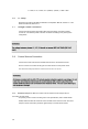
NOTE: Connections for relays, status inputs and communications are the same as for the PM175. See the
PM175 Installation and Operation Manual for connection drawings and instructions. Analog output is not
connected.
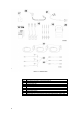
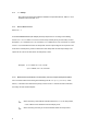
Figure 1-2 Detail of Nos. 2,3 and 16 in Figure 1-1 Figure 1-3 Detail of No. 12 in Figure 1-1
Figure 1-1 Standard Contents of EDL175
1
EDL175 Display
2
PM175 Status Inputs Connector - see Figure 1-2 for detail
3
PM175 Relays Connector - see Figure 1-2 for detail
4
Communication Port (RS-232)
5
Low battery LED “BAT LOW” (red, blinking) and Buzzer
6
AC Power LED (green)
7
Battery LED “BAT” (red)
8
Slide switch operating voltage supply
9
Battery and Battery Fuse
10
Battery Voltage measurement sockets
11
Voltage inputs
12
Current Terminals
13
Current Inputs
14
Power Supply Socket & Fuse Housing
15
Network neon light
16
PM175 Analog I/O (Option)