EDL175 Portable Event & Data Logger-Extended Range Installation & Operation Manual BG0447 REV.
LIMITED WARRANTY The manufacturer offers the customer a 24-month functional warranty on the instrument for faulty workmanship or parts from date of dispatch from the distributor. In all cases, this warranty is valid for 36 months from the date of production. This warranty is on a return to factory basis. The manufacturer does not accept liability for any damage caused by instrument malfunction.
Table of Contents 1. The Portable Event & Data Logger - Extended Range............................................................ 4 2. Installation .............................................................................................................................. 8 2.2 Connecting to the Electrical Network ..............................................................................................8 2.3 Connecting Voltage and Current Inputs.......................................................
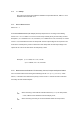
The EDL175 Portable Event & Data Logger - Extended Range measures, records and analyzes events and data of electrical network parameters. Being mobile, it enhances efficiency by enabling onsite identification of power problems. The EDL175 meets the requirements of a wide range of applications, from events analysis to energy auditing and load profile recording over a period of time.
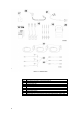
Figure 1-1 Standard Contents of EDL175 1 EDL175 Display 2 PM175 Status Inputs Connector - see Figure 1-2 for detail 3 PM175 Relays Connector - see Figure 1-2 for detail 4 Communication Port (RS-232) 5 Low battery LED “BAT LOW” (red, blinking) and Buzzer 6 AC Power LED (green) 7 Battery LED “BAT” (red) 8 Slide switch operating voltage supply 9 Battery and Battery Fuse 10 Battery Voltage measurement sockets 11 Voltage inputs 12 Current Terminals 13 Current Inputs 14 Power Supply So
Figure 1-5 EDL175 Dimensions PM172 Series 16 16a 17 18 19 20 21 22 23 24 25 6 EDL175 Installation and Operation Manual Series PM175 Installation and Operation Manual Series PM175 CD Current Clamps Set Voltage Probe Set Case for Clamps and Cable Communications Cable Power Supply Cord FLEX current sensors Connection Cables for FLEX current sensors Special cables for current clamps for low current measurement (100mA-10A)
Read through this section carefully before connecting the EDL175 to the circuit being tested. 2.1 Location The distance between the EDL175 and the current lines must be at least half a meter (1.6 feet) for current lines carrying up to 600A, and at least one meter (3.3 feet) for currents between 600A and 2000A. 2.2 Connecting to the Electrical Network Connect the EDL175 to the AC power supply using the Power Supply Cord (No. 22 on Figure 1-3). Turn the slide switch (No. 8 on Figure 1-1) ON. 2.
2.5 CT Setup Set up the CT according to the PM175 Installation and Operation Manual, Table 4-1 or the PASUser’s Manual, Section 6.1.1. 2.5.1 Normal Measurement Set the CT = 1. 2.5.2 Direct Measurement (via clamps) All clamps require the CT according to the following formula: CT = I1ncl / I2ncl where: I1ncl and I2ncl are the clamp nominal primary and secondary currents.
IP = 3000, IS = 5, Ic=1000, CT = (3000/5) • (1000/1) • 0.005 = 3000. 2.6 PT Setup Set the PT according to the PM175 Installation and Operation Manual, Section 4.1 or the PAS User’s Manual, Section 6.1.1. 2.7 Voltage Probes Connection Connect the voltage probes to the EDL175 through the voltage connectors marked V1/V2/V3/VN. Connect the probes to the line conductors according to the power system configuration. 2.
2.8. 2 2.8. 3 Special Cables The manufacturer's special cables, together with the standard clamps, enable the EDL175 to perform measurements on high voltage lines via existing current transformers with 5A nominal secondary current by measuring the output of the current transformers. Standard FLEX Current Sensors The EDL175 can work with all standard FLEX and clamp current sensors which have a voltage output up to 3V RMS.
3.3 Battery Voltage Measurement The amount of remaining battery charge can be estimated by checking battery voltage (Vbat). This is done by connecting an external voltmeter with internal resistance of greater than 1M_ to the battery measurement sockets (see Figure 1-1, no. 10). If Vbat _ 12V, the battery is operating normally. If Vbat _ 11V, the battery is LOW. If Vbat_10.5V, the battery is fully discharged. Power supply: 100-240 VAC, 45-65 Hz, 30 VA. Battery: rechargeable; 12V/1.2Ah DC.
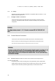
Figure 2-2 Three wire direct connection with special cable using 2 CTs (2-element), Wiring Mode=3dir2 13
Figure 2-3 Four Wire WYE Direct Connection Using 3 CTs (3-element) Wiring Mode = 4LL3 or 4Ln3 14
Figure 2-5 Four Wire WYE Connection with special cables using 3 PTs, 3 CTs (3-element) Wiring Mode = 4LL3 or 4Ln3 Figure 2-4 Four Wire WYE Direct Connection with special cables using 3 CTs (3-element) Wiring Mode = 4LL3 or 4Ln3 15
Figure 2-6 Three Wire Open Delta Connection using 2 PTs, 2 CTs (2-element) Wiring Mode = 3OP2 16
Figure 2-7 Three Wire Open Delta Connection with special cables using 2 PTs, 2 CTs (2-element) Wiring Mode = 3OP2 17
Figure 2-8 Three Wire Open Delta Connection with special cables using 2 PTs, 2 CTs (2-element) Wiring Mode = 3OP2 18
Figure 2-9 Four Wire Wye Connection with special cables using 2 PTs, 3 CTs (2½-element) Wiring Mode = 3LL3 or 3Ln3 19
Figure 2-10 Three Wire Open Delta Connection with special cables using 2 PTs, 3 CTs (2½-element) Wiring Mode = 3OP3 20
Figure 2-11 Four Wire Delta Direct Connection using 3 CTs (3 element) Wiring Mode = 4LL3 or 4Ln3 21
Figure 2-12 Four Wire Delta Direct Connection with special cables using 3 CTs (3 element) Wiring Mode = 4LL3 or 4Ln3 22
䘀椀最甀爀攀........................... ............................................................................. ............................................................................................. ............................................................................. ....................................................................... ............................................................................... ......... .................................................................