
User guide

Chapter 7 Viewing Status Information
64
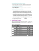
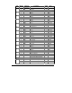
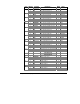
7.2 Status Display Formats
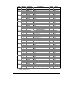
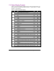
Table 7-1 lists all the displays available from the Status Information Menu. The
display windows are labeled in the table as follows: 1 = upper window, 2 = middle
window, 3 = lower window.
Table 7-1 Status Information Display
Page Window Parameter Digits Unit
1 PFC Label
2 PFC operation mode (see Table 7-2) 4
1
3 PFC operation status (see Table 7-3) 4
1 diAG Label
2
2
3 Device diagnostics: Err (device fault)/nonE 4
1 PHAS Label
2 rOt Label
3
3 Phase rotation sequence (POS/NEG/ERR) 4
1 rEL Label
2 Relay #1 - #4 status 4
4
3 Relay #5 - #8 status 4
1 St.In Label 5
3 Status input 1
1 Cnt.1 Label 6
3 Event/Time counter #1 5
1 Cnt.2 Label 7
3 Event/Time counter #2 5
1 Cnt.3 Label 8
3 Event/Time counter #3 5
1 Cnt.4 Label 9
3 Event/Time counter #4 5
1 CYC.1 Label 10
3 PFC relay operation (switching cycle) counter #1 5
1 CYC.2 Label 11
3 PFC relay operation (switching cycle) counter #2 5
1 CYC.3 Label 12
3 PFC relay operation (switching cycle) counter #3 5
1 CYC.4 Label 13
3 PFC relay operation (switching cycle) counter #4 5
1 CYC.5 Label 14
3 PFC relay operation (switching cycle) counter #5 5
1 CYC.6 Label 15
3 PFC relay operation (switching cycle) counter #6 5
1 CYC.7 Label 16
3 PFC relay operation (switching cycle) counter #7 5
1 CYC.8 Label 17
3 PFC relay operation (switching cycle) counter #8 5