
User guide

Chapter 1 Introduction 5
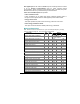
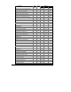
Output Parameter Dis-
play
Com
Analog Pulse Alarm
Real-time Harmonic Values
RT voltage THD per phase √ #$
RT current THD per phase √ #$
RT current TDD per phase √ #$
RT K-Factor per phase √ #$
Average Harmonic Values
Average Voltage THD per phase √ √
Average Current THD per phase √ √
Average Current TDD per phase √ √
Average K-Factor per phase √ √
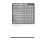
Fundamental Frequency Values (H01)
Voltage & current per phase √
kW, PF per phase √ √
kvar, kVA per phase √
Total kW, PF √ √
Total kvar, kVA √
Phase Rotation √ #$
Counters √ √
Status Input √ √ #$
Relay Status √ √
Remote Relay Control √
Alarm Trigger Status √ #$
Self-Diagnostic Tests √ √
For 4Ln3 and 3Ln3 wiring configurations line to line and line to neutral voltages are
displayed and transmitted via communication simultaneously and can be used as triggers
for alarm set points; analog output uses line to neutral voltages. For other configurations
only line to line voltages are used.