C192PF8-RPR Power Factor Manager & Reactive Power Regulator Installation and Operation Manual BG0347 Rev.
C192PF8-RPR Power Factor Manager and Reactive Power Regulator Installation and Operation Manual
LIMITED WARRANTY The manufacturer offers the customer an 24-month functional warranty on the instrument for faulty workmanship or parts from date of dispatch from the distributor. In all cases, this warranty is valid for 36 months from the date of production. This warranty is on a return to factory basis. The manufacturer does not accept liability for any damage caused by instrument malfunction.
The secondary of an external current transformer must never be allowed to be open circuit when the primary is energized. An open circuit can cause high voltages, possibly resulting in equipment damage, fire and even serious or fatal injury. Ensure that the current transformer wiring is made through shorting switches and is secured using an external strain relief to reduce mechanical strain on the screw terminals, if necessary.
Table of Contents Chapter 1 Introduction....................................................................... 1 1.1 1.2 About This Manual .................................................................................... 1 About The C192PF8-RPR .......................................................................... 1 Chapter 2 Installation......................................................................... 7 2.1 2.2 Mechanical Installation .....................................................
Chapter 1 Introduction 1. 1.1 About This Manual This manual is intended for the user of the C192PF8-RPR Power Factor Manager and Reactive Power Regulator. The C192PF8-RPR is a multi-function microprocessor-based instrument used for power factor or reactive power correction and for the measurement, monitoring, and management of electrical parameters in low-voltage and mid-voltage power systems. This chapter gives an overview of this manual and an introduction to the C192PF8-RPR.
• • • • • • • • Manual, self-adapting automatic and optimizing automatic operation Full four-quadrant operation Selectable target power factor or reactive power setpoints Two PFC setpoint ranges for day and night operations selectable via a status input Target power factor range from 0.5 (inductive) to -0.
One digital input can be used as a status input for monitoring external contacts or as an external synchronization input for power demand interval synchronization. When no external synchronization pulse is provided, the power demand interval can be synchronized through communications. Three user-selectable options are provided: Power calculation mode Power calculations can be made using directly measured reactive power or through non-active power based on direct apparent power measurements.
Parameter Apparent power accumulated demand Active power demand Active power sliding demand Apparent power demand Apparent power sliding demand Active power predicted demand Apparent power predicted demand Active power maximum demand Apparent power maximum demand Energy Per Phase Active energy import per phase Reactive energy import per phase Apparent energy per phase Total Energy Total active energy import Total active energy export Total reactive energy import Total reactive energy export Total reactive e
Parameter Real-time Harmonic Values RT voltage THD per phase RT current THD per phase RT current TDD per phase RT K-Factor per phase Average Harmonic Values Average Voltage THD per phase Average Current THD per phase Average Current TDD per phase Average K-Factor per phase Fundamental Frequency Values (H01) Voltage & current per phase kW, PF per phase kvar, kVA per phase Total kW, PF Total kvar, kVA Phase Rotation Counters Status Input Relay Status Remote Relay Control Alarm Trigger Status Self-Diagnostic T
Instrument Dimensions Figure 1-1 C192PF8-RPR Dimensions 6 Chapter 1 Introduction
Chapter 2 Installation 2. 2.1 Mechanical Installation Prepare the panel cut-out, 136 x 136 mm, prior to mounting. STEP 1: Place the instrument through the cut-out. STEP 2: Assemble the latches onto the outer wall of the enclosure. STEP 3: Tighten the screws.
2.2 Electrical Installation Before installation ensure that all incoming power sources are shut OFF. Failure to observe this practice can result in serious or even fatal injury and damage to equipment. Connections to the C192PF8-RPR are made via terminals (voltage and current inputs, power supply, communication, relay and analog output) as shown in Figure 2-2. 2.2.
Figure 2-2 C192PF8-RPR Connections - Rear View Chapter 2 Installation 9
2.2.5 Wiring Configurations Wiring Configuration (See parameter setup instructions in Section 4.
Figure 2-4 Four Wire WYE Direct Connection Using 3 CTs (3-element) Wiring Mode = 4LL3 or 4Ln3 Figure 2-5 Four Wire WYE Connection Using 3 PTs, 3 CTs (3-element) Wiring Mode = 4LL3 or 4Ln3 Chapter 2 Installation 11
Figure 2-6 Three Wire Open Delta Connection Using 2 PTs, 2 CTs (2-element) Wiring Mode = 3OP2 12 Figure 2-7 Three Wire Open Delta Connection Using 2 PTs, 3 CTs (2½-element) Wiring Mode = 3OP3 Chapter 2 Installation
Figure 2-8 Four Wire WYE Connection Using 2 PTs, 3 CTs (2½-element) Wiring Mode = 3Ln3 or 3LL3 Figure 2-9 Four Wire Delta Direct Connection Using 3 CTs (3 element) Wiring Mode = 4LL3 or 4Ln3 Chapter 2 Installation 13
Figure 2-10 Three/Four Wire Direct Connection Using 1 CT Wiring Mode = 2LL1 2.2.6 Relay Eight relays are provided for capacitor bank control (or energy pulsing/alarms).
2.2.7 Status Input One status input is provided for status monitoring or external synchronization input for power demand period. Figure 2-12 Status Input Connection 2.2.8 Analog Output The C192PF8-RPR provides one optically isolated analog output with current output options of 0-20 mA and 4-20 mA (current loop load of up to 500 Ohm). The analog output must be used with a 24 V DC external power supply.
2.2.9 Communications The C192PF8-RPR is provided with an RS-232 or RS-485 communication port. Figures 2-14 through 2-18 illustrate the connections.
9-PIN DB9 FEMALE CONNECTOR RS-232 15 POWERMETER 13 14 SG GND TxD RxD RxD TxD DSR DTR RTS CTS 5 2 3 IBM PC/COMPATIBLE 6 4 7 8 c99-11015 Figure 2-17 RS-232 Simple 3-Wire Computer Connection, 9-pin Figure 2-18 RS-485 Multi-drop Computer Connection NOTE: Where the manufacturer's RS-232/RS-485 converter is used on a computer connection, R1 is not applicable since it is built in to the converter.
Chapter 3 Using The Menus 3. Press and release appear: Press Press SELECT to enter the setup mode. The primary menus will StA - Status Information Menu (see Chapter 6) OPS - Setup Options Menu CHG - Setup Change Menu (see Chapter 4) SELECT again to activate the window of the desired primary menu. ENTER. Select CHG to initialize or modify the instrument setup, or to clear the accumulated values stored in the instrument. Entry to this menu can be protected by a password.
SELECT ENTER Status Information StA Setup Options ENTER OPS Setup Change Password CHG PASS PFC Manual Mode PFC.H PFC Setup PFC Reset Functions rSt Manual Relay Control rELc Basic Setup Event Setpoints SetP Scrolls options forward Scrolls options backward Status Inputs Cnt.1 PulS Quits menu/sub-menu rEL Port Aout ESC PHAS Relay Status St.
Chapter 4 Setup Menus 4. CHAPTER 3 SETUP MENUS NOTE: Instrument setup can be performed directly on the front panel using the setup menus or via communications using PAS communication software. PAS is supplied with your instrument and provides full setup capabilities for your instrument. For information on using PAS, refer to the user documentation supplied with your instrument.
Table 4-1 Basic Setup Options (∗ default setting) Code ConF Pt Ct d.P n.dp A.
NOTES 1) The maximum value for CT PRIMARY CURRENT × PT RATIO is 10,000,000. If this product is greater, power related values will be zeroed. 2) Always specify WIRING MODE, PT RATIO and CT PRIMARY CURRENT prior to setting up alarm setpoints, otherwise the alarm/event setpoints which use these parameters will automatically be disabled. 3) You will not be able to change the WIRING MODE, PT RATIO and CT PRIMARY CURRENT when the PFC is in operating state (see Section 4.13). 4.
Code Parameter Options 8E∗ CPtb ASCII compatibility mode diS∗, En Description 8 bits, even parity Disables/enables ASCII compatibility mode. For more information, see ASCII Communications Protocol Reference Guide 4.3 Digital Input Setup Menu SELECT CHG ENTER dinP ENTER This menu is used to set up a digital input provided by the C192PF8-RPR.
4.4 Analog Output Setup Menu [This section is relevant to instruments ordered with this option.] CHG SELECT Aout ENTER ENTER This menu allows you to set up an output value and its zero and full scales for the internal analog output. Table 4-3 explains the analog output setup options, and Table 4-4 lists all measurement parameters that can be directed to analog output.
Table 4-3 Analog Output Setup Options Code Option Description OutP Lo Output parameter The output parameter for the analog output channel Zero scale (0/4 mA) The reading of the parameter corresponding to a zeroscale current output Hi Full scale (1/20 mA) The reading of the parameter corresponding to a full-scale current output Table 4-4 Analog Output Parameters Code nonE r. U 1 r. U 2 r. U 3 r. C1 r. C2 r. C3 r. P r. q r. S r. PF r. PF.LG r. PF.Ld r.
Vmax (690 V input option) = 828.0 V Vmax (120 V input option) = 144.0 V Pmax = (Imax × Vmax × 3) [kW x 0.001] @ wiring modes 4Ln3, 3Ln3 Pmax = (Imax × Vmax × 2) [kW x 0.001] @ wiring modes 4LL3, 3OP2, 3dir2, 3OP3, 3LL3 NOTE: Pmax is rounded to nearest whole kW units. If Pmax is more than 9999.000 kW, it is truncated to 9999.000 kW Wiring via PTs (PT Ratio > 1): Vmax (690 V input option) = 144 × PT Ratio [V] Vmax (120 V input option) = 144 × PT Ratio [V] Pmax = (Imax × Vmax × 3)/1000 [MW x 0.
Code rE.EE rE.Et AP.Et Parameter Reactive energy export Reactive energy total Apparent energy total Units kvarh export (capacitive) kvarh total (absolute) kVAh total NOTES 1. You will not be able to store your setup in the instrument if you assigned a parameter to a relay output with a zero number of unit-hours per pulse. 2. If a relay you allocated for pulsing has been manually operated or released, it reverts automatically to normal operation. 3.
SP 1 On d 5 SP 1 OFFd 10 SP 1 Act rEL.1 Operate delay } } } } Release delay } The delays before operation (On d) and release (OFFd) are set at 5 seconds and 10 seconds respectively. Setpoint action The action to be triggered is operation of relay #1. To select a setpoint: Scroll to the desired setpoint using the up/down arrow keys. To view the setup options for the setpoint: Press SELECT to activate the middle window. Use the up/down arrow keys to scroll to the desired setup option.
Table 4-6 Setpoint Setup Options (middle window) Code Option trig Trigger parameter On OFF Operate limit Release limit On d Operate delay OFF d Release delay Act Setpoint action Description The measurement parameter or signal to be monitored by the setpoint. The threshold at which the setpoint becomes operative. The threshold at which the setpoint is released (becomes inoperative). The time delay (0.1 second resolution) before operation when the operate condition is fulfilled. The time delay (0.
Code A. Lo.C3 A. Hi. U A. Hi. LU A. Lo. U A. Lo. LU A. Hi. C A. Lo. C A. Hi.P.i A. Hi.P.E A. Hi.q.i A. Hi.q.E A. Hi. S A. PF.LG A. PF.Ld Ar neU.C Ar Hi.Fr Ar Lo.Fr Hi d.U1 Hi d.U2 Hi d.U3 Hi d.C1 Hi d.C2 Hi d.C3 Hi d.P Hi d.S Hi Sd.P Hi Sd.S Hi Ad.P Hi Ad.S Hi Pd.P Hi Pd.
The No-Volt trigger is intended for the use as a fast setpoint override condition for PFC operations in order to protect the capacitor banks against voltage interruptions. When used with the Hard Switch-Off action, it can de-energize the output relays in approximately 25 ms. This avoids bringing the still charged capacitors back after the voltage is restored. When used with other setpoint actions, this trigger can provide the response time to alarm conditions at 25-75 ms.
not be affected. After the alarm condition passes, the PFC will return to automatic operation after the safety delay which is 50 times the power factor setpoint operate delay (see Note to Table 4-11). The Stop action freezes the PFC operations in automatic operation modes. The PFC avoids any automatic switching operations on the capacitor banks while the alarm condition is present. This action does not affect operations in the Manual/Remote mode. Alarm relays operate in unlatched mode.
4.8 Display Setup Menu SELECT CHG diSP ENTER ENTER This menu allows you to view and change display properties. Table 4-9 lists available options with their code names and applicable ranges. Table 4-9 Display Options (∗ default setting) Display Code Parameter Options diSP UPdt Display update time 0.1 - 10.0 s (0.
To select a display option: Press SELECT to activate the middle window, and then use the up/down arrow keys to scroll to the desired option. To change the display option: Press SELECT to activate the lower window. Use the up/down arrow keys to set the desired option. Press ENTER to store your new setting or press ESC to leave your previous setting unchanged. To quit the display setup menu: From the middle window, press ESC or ENTER . 4.
Code Ph.En Parameter Phase energy measurements Options diS*, En Description Enables/disables measurements of energies per phase Power calculation mode (P.
4.10 Access Control Menu SELECT CHG ENTER AccS ENTER This menu can be only accessed via the Setup Change Menu (CHG). It is used in order to: • change the user password • enable or disable password check To view an option setting: Press SELECT to activate the middle window. Use the up/down arrow keys to scroll to the desired option (PASS or CtrL). Password Setting Password Protection Control AccS AccS PASS CtrL 8780 OFF To change the password: Press SELECT to activate the lower window.
4.11 Reset/Synchronization Menu SELECT CHG ENTER rSt ENTER This menu allows you to reset to zero the accumulators and Min/Max registers in your instrument, and also to synchronize the power demand interval. The menu can be only accessed via the Setup Change Menu (CHG). If the reset is disabled from the Basic Setup Menu (see Section 4.1), you will not be able to enter this menu.
data display mode (see Section 5.1), and reset of counters from the Status Information Menu (see Section 6.1) without entering the reset menu. 2. If you select the d.Snc entry, take into consideration the following: a) If the power demand period is specified in minutes (see Section 4.1, Basic Setup Options), this action provides synchronization of the instrument’s internal timer.
4.13 PFC Setup Menu SELECT CHG ENTER PFC ENTER This menu allows you to configure the PFC setup options and to set the PFC operation mode. Table 4-11 lists the PFC setup options, their code names and applicable ranges. For more information on the PFC options and operation, refer to Chapter 5, PFC Operation. PFC To select and view a setup option: run Press SELECT to activate the middle window Use the up/down arrow keys to scroll to the desired option.
Code U.CAP Nominal voltage of the capacitor banks L.PF1 Low target PF1 (in PFC mode) High target PF1 (in PFC mode) Low target PF2 (in PFC mode) High target PF2 (in PFC mode) Low target kvar 1 (in RPR mode) High target kvar 1 (in RPR mode) Low target kvar 2 (in RPR mode) High target kvar 2 (in RPR mode) Setpoint operate delay, sec H.PF1 L.PF2 H.PF2 L.rE1 H.rE1 L.rE2 H.rE2 OP.d On.d OFF.d rEc.
Code CAP3 Parameter Size of the capacitor bank #3, kvar CAP4 Size of the capacitor bank #4, kvar CAP5 Size of the capacitor bank #5, kvar CAP6 Size of the capacitor bank #6, kvar CAP7 Size of the capacitor bank #7, kvar CAP8 Size of the capacitor bank #8, kvar Options On, nonE, 1 to 10000 kvar (1500∗) On, nonE, 1 to 10000 kvar (1500∗) On, nonE∗, 1 to 10000 kvar Description Power rating of the capacitor bank. nonE = not used, On = permanently switched in Power rating of the capacitor bank.
4. The target power factor limits are always specified for the I and IV quadrants regardless of the location of the instrument on the source or load side. The PFC will automatically account for the direction of power flow providing full four-quadrant operation. 5. If both target power factor limits are specified for the same quadrant, the high power factor limit should never be less than the low limit.
4.14 PFC Manual Mode Menu SELECT CHG PFC.H ENTER ENTER This menu allows you to manually operate (connect or disconnect) the PFC capacitor banks in progressive order by entering commands from the front panel. The menu can be only accessed via the Setup Change Menu (CHG) if the PFC is running in Manual Mode (see Section 4.13, PFC Setup).
Chapter 5 PFC Setup and Operation 5. PFC Setup and Operation This chapter describes how to setup the Power Factor Controller for your application and explains its important features. Brief instructions are included for certain setup and display operations. Complete setup instructions are found in Section 4.13, PFC Setup; complete display information is found in Chapter 6 (Data Display) and Chapter 7 (Viewing Status Information). 5.
To specify the bank as a permanently switched bank, set the bank size parameter to On (see Section 4.13, PFC Setup). The permanently switched banks are switched in automatically when the PFC is put into either manual or automatic operation mode and before a switching program begins, and are switched out when the PFC shuts down, following all switching and re-connection time delays.
the target. When no leading (capacitive) target power factor is allowed, only combinations that provide lagging (inductive) power factor will be checked. The banks are connected and disconnected starting from the low-size banks, following all pre-set switching and re-connection delays. Alternation of switching operations is provided when needed to avoid excessive deviation from the target power factor. The optimization program is complete when one of the following is true: 1.
Shutting the PFC Down From the PFC setup menu, set the PFC operation mode to OFF. This will put the PFC into Shut Down mode. Shut Down mode provides step-by-step disconnection of all the capacitor banks that are under the PFC control. The banks switch out progressively, following disconnection intervals (switch-off delays). After all the banks are switched out, the PFC is put into OFF state. 5.2.
PFC will not take into account the status of the digital input. The second setpoint will not even appear in the PFC setup menu. If you want to use different target setpoints and switch them depending on the time schedule or another external condition, specify the operational setpoints as SP1-2. In this event, both SP1 and SP2 setpoint ranges will be available for setup, and should be defined for proper operation.
defined setpoint operate delay. This makes the trigger less sensitive to fast changes in load thus avoiding excess switching. The operate delay timer is reloaded each time the measured power factor oversteps the setpoint range limits. The allowable range for the operate delay is 1 to 3600 sec. The default value is 3 sec. Low Lacking Reactive Power To avoid excess cycling, the power factor setpoint will not trigger the PFC if the lacking reactive power is less than 0.
Normally, the capacitors discharge through fixed resistors that are connected to the capacitors directly or via auxiliary contacts of the contactors. Refer to the capacitor data sheet for the recommended discharge time for your capacitors. The re-connection delay can be adjusted in the range of 3 to 3600 sec. The default setting is 300 sec. 5.2.
The C192PF8-RPR allows you to choose between manual and automatic adjustment of the capacitor bank powers.
5.3 Capacitor Banks Protection 5.3.1 PFC Protective Actions The reason for the PFC protection mechanism is to protect the capacitor banks and contactors against harmful conditions that would lead to extremely high overvoltage, or would cause undesirable effects such as high transient voltages and currents and high harmonics.
5.3.2 PFC Protection Setpoints Protection against Voltage Interruptions The fast disconnection of the capacitor banks is required in the event of shortterm voltage interruptions that would cause damage to the still-charged capacitors when the voltage is restored. The No-Volt alarm override condition (see Table 4.6) along with the Hard SwitchOff action can de-energize the output relays in approximately 25 ms whenever voltage interruption is detected.
Protection against High Harmonics High THD protection prevents damage to capacitors at high levels of voltage harmonics, which can be caused by voltage resonance at a higher frequency. The effect of the high THD setpoint protection is limited progressive disconnection of the capacitor banks until resonance conditions disappear, and then, after a long safety delay, returning the PFC into normal operation. The setpoint can operate at high THD of 3 to 300% depending on the network conditions with a delay of 0.
Chapter 6 Data Display 6. 6.1 Navigating in the Display Mode The front panel has a simple interface that allows you to display numerous measurement parameters in up to 43 display pages. For easier reading, the parameters are divided into three groups, each accessible by a designated key.
Alarm/Man Mode LED This LED has two functions. The blinking LED indicates that the PFC is operating in Manual Mode. The constantly lit LED gives you an alarm indication. It is controlled by the alarm/event setpoints (see Section 4.6) and operates in latched mode. Even if alarm conditions are no longer present, the alarm LED will continue to warn. To clear the alarm LED, press the up and down arrow keys simultaneously for 5 seconds. Auto Scroll If display Auto Scroll option is enabled (see Section 4.
Selecting Total Harmonic Measurements Press the THD/TDD key until the THD or TDD LED is illuminated. Use the up/down arrow keys to scroll through the different harmonic parameters. Selecting Energy Measurements Press the ENERGY key. Use the up/down arrow keys to scroll through the different energy readings. Fast Reset of Accumulated Data Select a display page where the data you want to reset is displayed.
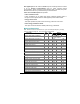
Page Window 5 1 2 3 1 2 3 1 2 3 1 2 3 1 2 3 1 2 3 1 2 3 1 2 3 1 2 3 1 2 3 1 2 3 1 2 3 1 3 1 3 6 7 8 9 10 11 12 13 14 15 16 17 18 1 58 1 2 3 Indicator LED A NEUT Hz kW PF kW kVA kvar PF kW kVA kvar PF kW kVA kvar PF kvar kVA kW PF kW PF kW PF kW MIN V1/V1-2 V2/V2-3 V3/V3-1 Parameter Digits Neutral current Frequency Total kW Power factor L1 Ph.L1 kW L1 kVA L1 Ph.L1 kvar L1 Power factor L2 Ph.L2 kW L2 kVA L2 Ph.L2 kvar L2 Power factor L3 Ph.L3 kW L3 kVA L3 Ph.
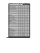
Page Window 2 1 2 3 1 2 3 1 2 3 3 4 5 6 7 8 9 10 11 1 2 3 1 2 3 1 2 3 1 2 3 1 2 3 1 2 3 1 2 3 2 1 3 1 2 3 1 2 3 1 2 3 Chapter 6 Data Display Indicator LED A1 A2 A3 PF kVA kvar A NEUT Hz kW MAX V1/V1-2 V2/V2-3 V3/V3-1 A1 A2 A3 PF kVA kvar A NEUT Hz kW MAX DMD V1 V2 V3 A1 A2 A3 PF kVA kW THD V1/V1-2 V2/V2-3 V3/V3-1 A1 A2 A3 TDD A1 A2 A3 Parameter Digits Min. Min. Min. Min. Min. Min. Min. Min. Min.
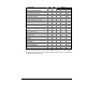
Page Window 1 1 2 3 1 2 3 1 3 1 2 3 1 2 3 MWh 1 2 3 1 2 3 1 2 3 1 2 3 1 2 3 1 2 3 1 2 3 1 2 3 1 2 3 MWh 2 3 4 5 6 7 8 9 10 11 12 13 14 Indicator LED Mvarh MVAh MWh Mvarh Mvarh MVAh MWh Mvarh MVAh MWh Mvarh MVAh Parameter Total Energies Ac.En. IP. MWh import rE.En. IP. Mvarh import AP.En. MVAh Ac.En. EP. MWh export rE.En. EP. Mvarh export Phase Energies Ac.En. IP.L1 MWh import L1 rE.En. IP.L1 Mvarh import L1 AP.En. L1 MVAh L1 Ac.En. IP.L2 MWh import L2 rE.En. IP.
When using direct wiring (PT Ratio = 1), voltages are displayed in 0.1 V units, currents in 0.01 A units, and powers in 0.001 kW/kvar/kVA units. For wiring via PTs (PT Ratio > 1), voltages are displayed in 1V units, currents in 0.01 A units, and powers in 0.001 MW/Mvar/MVA units. When the value width is over the window resolution, the right most digits are truncated By default, the maximum range for energy readings is 99,999,999 MWh/Mvarh/MVAh. Beyond this value, the reading will roll over to zero.
When the device detects a corrupted configuration setup or incompatible setup setting, it sets a corresponding fault bit in the diagnostics register, resets the corrupted setup to default and rises a critical (unrecoverable) error. Diagnostics status can be viewed through the Status Information Menu (see Section 7.2), and tested through a setpoint via the Device Fault trigger.
Chapter 7 Viewing Status Information 7. Through the Status Information Menu (StA), it is possible to view the status of various instrument features. 7.1 The Status Information Menu StA SELECT ENTER To enter the Status Information Menu: From the display mode, press SELECT to enter the Primary Selection Menu. Press SELECT to activate the StA window. Press ENTER . . To select a display page: Press the up/down arrow keys to scroll through the display pages.
7.2 Status Display Formats Table 7-1 lists all the displays available from the Status Information Menu. The display windows are labeled in the table as follows: 1 = upper window, 2 = middle window, 3 = lower window.
Table 7-2 PFC Operation Modes Code OFF Sh.dn Aut.1 Aut.2 HAnd Operation Mode The PFC is switched OFF The PFC is shutting down Self-adapting automatic operation mode Optimizing automatic operation mode Manual operation mode Table 7-3 PFC Operation Status Code ready ALAr busy Lo.rEA Ind.L CAP.
Appendix: Technical Specifications 8.
Environmental Conditions Operating temperature -20°C to +60°C (-4°F to +140°F) Storage temperature -25°C to +80°C (-13°F to +176°F) 0 to 95% non-condensing Humidity Construction Instrument body Case enclosure: flame resistant ABS & Polycarbonate Blend Dimensions: 144 x 144 x 86 mm ( 5.67 x 5.67 x 3.39 “) Mounting: 136 x 136 mm square cut-out (DIN 43700) Instrument weight 0.9 kg (2.04 lb.
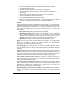
Measurement Specifications Parameter Voltage Line current Full scale 120V×PT @ 120V or 400V×PT @ 690V Rdg For Ln reading and for 3OP2/3OP3 wiring modes Accuracy, % Range FS Conditions 0.25 10% to 120% FS 0 to 999,000 V Display resolution (%Rdg) @ range Direct wiring (PT=1): 0.1 V @ 0.1V to 999.9 V Wiring via PTs (PT>1): 0.001 kV @ 0.001kV to 9.999 kV ≤0.1% @ 10.00 kV to 999.0 kV 208V×PT For LL reading @ 120V or except 3OP2/3OP3 690V×PT wiring modes @ 690V CT PRIMARY CURRENT Starting voltage 1.
Parameter Neutral (unbalanced) current Full scale CT PRIMARY CURRENT Rdg Accuracy, % FS Conditions 0.5 2% to 120% FS Range 0 to 9999 A Display resolution (%Rdg) @ range 0.01 A @ 0.01A to 99.99 A ≤0.1% @ 100.0 A to 9999 A Starting current 0.5% FS Ampere demand KW demand (block & sliding) KVA demand (block & sliding ) 999.9 Total Harmonic Distortion THD U (I), % U1 (I1) 100 Total Demand Distortion TDD (I), % Active energy Import & Export same as for current same as for kW same as for kVA 1.5 0.2 ≥ 0.
Index A accuracy, 70 active energy, 4, 70 active power, 3, 4, 35, 69 alarms, 14 ampere demand, 21, 30, 60 analog output, 2, 5, 8, 15, 24, 25 analog outputs, 22 B basic setup, 20, 39 burden, 67 C communications, 70 controller, 55 CT, 2, 21, 22, 25, 33, 69, 70 CT PRIMARY CURRENT, 22, 69, 70 current inputs, 8, 67 current transformers, 70 mounting, 1, 7 O open delta, 10, 21, 39, 40 options, 15 overload withstand, 67 P panel cut-out, 7 password, 2, 18, 36, 37, 57, 64 PComTest, 20 power, i, 2, 3, 4, 8, 15, 2