AX-8 Analog Expander Installation and Operation Manual BG0259 Rev.
AX-8 Analog Expander Installation and Operation Manual
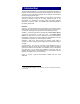
LIMITED WARRANTY The manufacturer offers the customer a 24-month functional warranty on the instrument for faulty workmanship or parts from date of dispatch from the distributor. In all cases, this warranty is valid for 36 months from the date of production. This warranty is on a return to factory basis. The manufacturer does not accept liability for any damage caused by instrument malfunction.
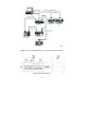
1 Introduction 1. The AX-8 Analog Expander is an instrument that enables Powermeters to interface with other devices that require analog signals. The AX-8 can be connected to any Powermeter equipped with an RS-422 communication port and analog expander option. The AX-8 provides up to 8 analog outputs. Two units can be connected in sequence, providing as many as 16 analog outputs with use of one 1 Powermeter .
RS-422/RS-485 UP TO 31 POWERMETERS ANALOG OUTPUT IN SYSTEM 290 HAR MON IC AN ALYZ ER POWER FA CTOR L 1 /L 1 2 L 2/L 23 L3 / L 3 1 1 2 3 4 5 6 7 8 + _ + _ + _ + _ + _ + _ + _ + _ MAX.DEMAND VOLTAGE CURR ENT S E L E CT A SATEC RE SE T MA X K VA MAX.DEMAND P AG I NG FREQUENCY KW Hz MW MAX.DEMAND K W H /M W H A KA MAX.AMP.DEMAND K VAR H/ MVA RH REACTIVE ENERGY S E LE CT A UNBALANCED CURRENT ACTIVE ENER GY V KV M VA MVA R REACTIVE POWER ACTIVE POW ER A KA MAX.AMP.
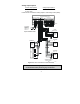
2 Field Setting 2. 2.1 Default Setting The Analog Expander is set by the dip switches S1 and S2 on the PCB located inside the AX-8 case. The default setting is as follows: Expander address Analog output range Protocol ASCII Data format Baud rate If you require a change to this setting, open 2.4 below and change the setting. 2.2 01 factory set as per order 8N (8 bit, no parity) 9600 bps the case as per Sections 2.2 - Changing the Communication Parameters (Firmware Version 0.10) 1.
1 3 4 6 5 7 8 R27 R25 R28 R30 R29 R24 + C18 R23 R18 R16 R14 ON + R26 R106 R107 R101 C101R103 R204 1 C204 R38 U102 ON R36 R35 C102 1 R110 R105 U101 R109 R104 R108 1 2 R43 C12 C13 1 8 1 7 + + D8 6 CE5 CE4 CE7 5 D7 4 +15V C14 R42 3 U6 2 L3 PC0117 REV.
3 Installation 3. 3.1 Mechanical Installation The AX-8 should be mounted in a dirt-free environment away from heat sources and high electrical fields. Mounting may be either standard DIN rail or wall mount. Only front access is required for wiring. 30 " 6. (3 3) EX PA N 7.3 (18 2 3" 6. 0 ) DE R AX PA NE L -8 8 4.6 5" " 18 5.1 ) 0 . 0 (13 01-05001-1 2.992" 4 1. (76.0) 6" 49 ) 6. 5.
SCREW LOCK WASHER AN AL OG EX PA ND ER AX - PA NE L 8 Figure 3-2 Wall Mounting 3.2 Electrical Installation For AX-8 connections to the power supply, communications and analog outputs, see Figures 3-3 (RS-422 network) or 3-4 (RS-485 network). IMPORTANT: It is recommended to solder the wire ends before attaching them to the connectors. Power Supply Use a dedicated breaker from a proper power source, from which the unit can be turned off.
Analog Output Options Current output options 0-20mA, 4-20mA Voltage output options 0-10V DC and ±10V DC 0-1mA, ±1mA Loads must be connected to analog outputs 1-8 according to their polarity.
ANALOG EXPANDER AX-8 PO WE R S UPP LY PO WE R M ET ER AC DC L N + _ NETW ORK ANALOG OUTP UTS RS- 422 RS- 422/RS-485 + + _ _ + + _ _ TX RX TX RX TX RX TX RX 1 + 2 _ + _ + 3 4 _ + _ + 5 6 7 8 _ + _ + _ + _ TX ON RX RX LOADS 1 5A POWER SUPPLY 110-230V AC/DC OR 48V DC * OR 24V DC * OR 12V DC * 2 3 4 5 6 7 8 MASTER (IBM PC OR PLC) -Tx *as per customer order -Rx +Tx +Rx RS-422/485 COMMUN. PORT R1 POWERMETER #1 NETWORK RS-422 COMMUN.
4 Operation 4. Refer to the Installation and Operation Manual of the specific Powermeter for instructions on Analog Expander and communication parameters setup. 4.1 Power Up Close the power feed breaker; the ‘ON’ LED will light up. 4.2 Communication When you program your powermeter to output data to external analog outputs, the powermeter periodically updates the AX-8 analog outputs (each 300-500 ms) via the pair of wires on the RS-422 communications link used for transmitting data.
Transmission Status LED Indication no transmission no LEDs lit up Powermeter to AX-8 single Rx LED (‘1’ in Figure 4-1) flashes RS-422: master to Powermeter Powermeter Tx LED (‘2’) flashes Powermeter to master Powermeter Rx LED (‘3’) flashes RS-485: master to Powermeter Powermeter to master Powermeter Rx and Tx LEDs flash NETWORK POWER METER RS-422 RS-422/RS-485 _ _ + + + + _ _ TX RX TX RX TX RX TX RX + TX RX RX 2 1 3 Figure 4-1 Detail of Communication LEDs on AX-8 10
5 Technical Specifications 5. Instrument serial communications Network serial communications Baud rate (bps) RS-422 RS-422 / RS-485 110, 300, 600,1200, 2400, 4800, 9600, 19200 > 95dB Inter-channel separation Galvanic isolation: Power Supply Communication Accuracy Temperature coefficient 2500V rms 1000V DC ±1.0% of full scale for current output up to 2500 Ω ±2.
Technical Specifications (continued) Standards UL File # E129258 CE-EMC: 89/336/EEC as amended by 92/31/EEC and 93/68/EEC CE-SAFETY: 72/23/EEC as amended by 93/68/EEC and 93/465/EEC Harmonized standards to which conformity is declared: EN55011:1991; EN50082-1:1992; EN61010-1:1993; A2/1995 ANSI C37.90.1 1989 Surge Withstand Capability (SWC) ANSI C62.