
User guide


16
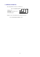
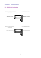
B.2 RS-422 Cable Configuration
B.2.1 RS-422 Connection
TxD
RxD
TxD
-
RxD
-
TxD
RxD
6
7
RxD'
TxD'
DB9 male connector
2
3
Series PM
-280/288/270/290
Powermeters
RxD-
TxD-
RxD
TxD
6
7
DB9 male connector
RxD-
TxD-
RxD
TxD
Series PM-290H
Powermeters
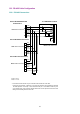
Series PM-170 Powermeters
8
9
14
15
16
17
DB25 male connector
1
1
1
GND
GND
GND
* A termination resistor should only be connected at the furthest end of the cable
COM
R1
R1,R2 - 120
*R2
R3,R4 - 1.2
k
Ω
Ω
**R3
**R4
** In RS-422
communication, a reference or common line should be used in addition to signal lines
use a reference line, place pull-down resistors R3 and R4
on both outputs of the driver to avoid
leaving the line floating when the line is idle
7
1771-DB BASIC module
4
5
16
14
18
25
for stable operation. Connect pin 1 of the instruments with pin 7
on the BASIC module. If you don't
DB25 male connector