
Installation Sheet

COMMERCIAL LED
DOWNLIGHT RETROFITS
Models: S11810, S11811, S11812, S11813,
S11814, S11815, S11816, S11817
Satco Products, Inc.
Brentwood, NY 11717
NEW CONSTRUCTION INSTALLATION
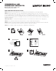
STEP 1: TURN OFF the electrical power at fuse or circuit breaker box before wiring xture to power supply. (Figure A)
STEP 2: Verify that supply voltage is correct by comparing it with the downlight specication. Open the connection box cover and
remove the appropriate knockout(s). Make wiring connections as per wiring diagram. (Figure B) Connect the hot power line (L) wire into
the wire lead from the Driver, connect the neutral (N) wire lead to the neutral wire lead from the driver. If using 0-10V dimming; connect
the purple (+) wire lead from the driver to the dimming control lead, connect the gray (–) wire lead from the driver to the dimming control
gray wire lead. (Figure B)
STEP 3: Important! The color temperature and light levels must be set on the xture before installation into the ceiling. (Figure C)
STEP 4: Connect the xture lead wire from the LED junction box securely to the xture wire lead. (Figure D)
STEP 5: The xture can now be inserted into the ceiling by compressing the two spring clips to an upright position and carefully slide
the xture into the ceiling hole until the xture trim ushes up against the ceiling surface. (Figure E)
STEP 6: Once assembly is complete, turn power ON to conrm xture is working properly.
© Copyright 2019 Satco Products, Inc. 12/19
A
Line (Black)
Neutral (White)
Ground (Copper)
DIM+ (Purple)
DIM– (Gray)
B
E
0-10V
Dimming
Wiring Diagram
D
2700K
3000K
3500K
4000K
5000K
900L
1200L
1750L
C