
Installation Sheet
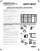

COMMERCIAL LED
DOWNLIGHT RETROFITS
Models: S11810, S11811, S11812, S11813,
S11814, S11815, S11816, S11817
Satco Products, Inc.
Brentwood, NY 11717
WARNING: Risk of Fire or Electric Shock
• This product must be installed in accordance with the applicable
installation code by a person familiar with the construction and
operation of the product and the hazards involved.
• TURN OFF the electrical power before proceeding.
• To reduce the risk of re and over-heating, secure all connections
are tight.
• To reduce the risk of death, personal injury or property damage
from re, electric shock, falling parts, cuts/abrasions, and other
hazards read all warnings and instructions included with and on
the xture box and all xture labels.
• Installation, service and maintenance of luminaries should be
performed by a qualied licensed electrician.
• This recessed downlight is intended to be connected to a properly
installed and grounded UL listed junction box.
• Do not install if product is damaged.
• Always wear gloves and safety glasses when removing downlight
from carton, installing, servicing or performing maintenance.
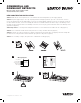
RETROFIT INSTALLATION
STEP 1: TURN OFF the electrical power at fuse or circuit breaker
box before wiring xture to power supply. (Figure A)
STEP 2: Locate a suitable position to install the xture and create
a hole in accordance to the dimensions. (Figure B)
NOTE: For NEW CONSTRUCTION see reverse for
installation instructions.
STEP 3: Verify that supply voltage is correct by comparing it with
the downlight specication. Open the connection box cover and
remove the appropriate knockout(s). Make wiring connections as
per wiring diagram. (Figure C) Connect the hot power line (L) wire
into the wire lead from the Driver, connect the neutral (N) wire lead
to the neutral wire lead from the driver. If using 0-10V dimming;
connect the purple (+) wire lead from the driver to the dimming
control lead, connect the gray (–) wire lead from the driver to the
dimming control gray wire lead. (Figure C)
STEP 4: Important! The color temperature and light levels must
be set on the xture before installation into the ceiling. (Figure D)
STEP 5: Connect the xture lead wire from the LED junction box
securely to the xture wire lead. (Figure E)
STEP 6: The xture can now be inserted into the ceiling by
compressing the two spring clips to an upright position and
carefully slide the xture into the ceiling hole until the xture trim
ushes up against the ceiling surface. (Figure F)
STEP 7: Once assembly is complete, turn power ON to conrm
xture is working properly.
INSTALLATION AND SAFETY INSTRUCTIONS
IMPORTANT: Read before installing xture. Retain for future reference.
Specications
Operating Temperature = -20C (-4F) to a maximum of +45C (+113F)
© Copyright 2019 Satco Products, Inc. 12/19
Model #
Ceiling Aperture
(Hole cut size)
Adjustable
Lumens
Adjustable
Color Temp. Volts
S11810,
S11814
4.10" (102mm)
600L/800L/
1020L
2700K
3000K
3500K
4000K
5000K
120-
277V
S11811,
S11815
5.90" (150mm)
900L/1200L/
1750L
S11812,
S11816
8.30" (211mm)
1600L/2000L/
2450L
S11813,
S11817
10.00" (254mm)
2500L/3000L/
3500L
A B
Line (Black)
Neutral (White)
Ground (Copper)
DIM+ (Purple)
DIM– (Gray)
C D
E F
0-10V
Dimming
Wiring Diagram
2700K
3000K
3500K
4000K
5000K
900L
1200L
1750L
• Avoid direct eye exposure to the light source while it is on.
• Damp location rated.