
Operating instructions
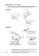


Selecting and Attaching ID Plates
The ID plate is to be selected and attached according to the specification block (configuration of scales) and the display and
control unit (terminal). For details of how to position the ID plate on the scales or tag holder, refer to the instructions in
"Plates and Markings".
If display and control units (terminals) of
type T
TA
, models C
CAIS1, CAISL1, CAIS2, CAISL2, CAIS3, CAISL3
are being used,
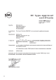
EC Type Approval Certificate No. T
T7899
, type S
SARTOCOWAT
is applicable.
ID plate for class
configurations
ID plate for class
configurations
If display and control units (terminals) of
type T
TN
, models C
CIS2, CSL2, CIS3, CISL3, type TN-X, model CISX3
,
type T
TN-Pro
, model C
Combics Pro
,
type i
isi10, isi20, isi30
, type Y
YAC01LA
, type Y
YAC01LP
, type Y
YAC01FC
, type Y
YAC02FC
,
PC with S
Sartorius Win Scale
software
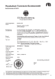
EC Type Approval Certificate No. D
D97-09-018
, type i
iso-TEST
is applicable.
ID plate for class
configurations
ID plate for class
configurations
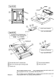
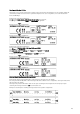
Select and Attach Plate Containing Metrological Data
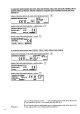
Plates with the metrological data Max, Min e and d must also be attached near to the display.
Select the plate with the Max, Min e and d metrological data that is suitable for the configuration, cut along the dotted lines
and attach above the display.
The transparent protective film must be stuck over the plate containing the metrological data. The tamper-proof plate
containing the metrological data does n
not
need verification seals.
Examples of attached plates containing metrological data for the possible configurations.
29