
User Manual

6
7
5
4
3
2
1
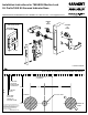
CENTERLINE OF
LOCKBODY
2-1/2”
1-3/8”
2-3/4”
LOW SIDE
OF DOOR
INSIDE LHRB
OUTSIDE RH
NO BEVEL
DOOR
HIGH SIDE
OF DOOR
INSIDE LH
OUTSIDE RHRB
1/2” DIA. HOLE
O
C
C
O
C
C
V
A
C
82-4050
82-4051
FOLD HERE ACCORDING TO DOOR HAND AND BEVEL
TOP
CYLINDER
LEVER OR KNOB
10
9
8
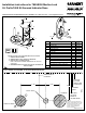
INSTRUCTIONS FOR CHANGING INDICATOR SLIDES
1. REMOVE PHILIPS SCREW.
2. REMOVE BACK PLATE, HUB PLATE AND SLIDE.
3. REPLACE WITH ALTERNATE SLIDE.
NOTE: CHECK FOR PROPER ORIENTATION OF VAC/OCC
SLIDE TEXT.
4. REASSEMBLE HUB PLATE AND BACK PLATE, SECURE WITH
PHILIPS SCREW.
Item Description Qty.
Part
Number
1 Indicator Housing 1 82-0604
2 Spindle Hub 1 82-0605
3 Spindle 1 77-1195
4
Red/White Slide 1 82-4050
VAC/OCC Slide 1 82-4051
5 Hub Plate 1 82-0590
6 Back Plate 1 82-0606
7 #6-32 x 3/16” MS 1 01-4553
8 Mounting Adapter 1 91-2151
9
Mounting Post, 185S-1, 1-3/8” Door 2 81-0017
Mounting Post, 185S-2, 1-3/4” Door 2 81-0723
Mounting Post, 185S-3, 2” Door 2 92-0069
Mounting Post, 185S-4, 2-1/4” Door 2 82-0539
10 TORX Screw 1 01-1421
FOR INSTALLATION ASSISTANCE CALL SARGENT AT 1-800-727-5477 / www.sargentlock.com
Installation Instructions for 7800/8200 Mortise Lock
50- Prex/185S Kit Secured Indicator Rose
Copyright © 2010, Sargent Manufacturing
Company, an ASSA ABLOY Group company.
All rights reserved. Reproduction in whole
or in part without the express written
permission of Sargent Manufacturing
Company is prohibited.
A7671:A 11-15-10