
User's Manual

The Sapling Company, Inc.
1633 Republic Road
Huntingdon Valley, PA 19006
USA
+1 215.322.6063 P.
+1 215.322.8498 F.
www.sapling-inc.com
10
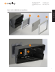
Wiring Information
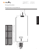
Wiring and Jumper Settings (3200 Series)
**Jumper Position
JP 1
JP 4
JP 5
JP 6
JP 2
JP 3
Power Settings
1
4
5
2
3
24VAC @ 0.35A (ORG)
120VAC or 240VAC @ 0.1A (BLK)
No Connection
120VAC or 240VAC @ 0.1A (WHT)
24VAC @ 0.35A (YEL)
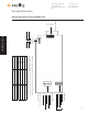
Elapsed Timer
5
2
1
4
3
No Connection
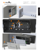
TXD (Blue&Blue/White)
Common (Green&Green/White)
RXD (Orange&Orange/White)
3.3V@0.1A (Brown&Brown/White)
P1 - Sync Inputs
P2 - User Inputs
P3 - Relay Output
4
3
2
1
*Relay 1 N.O.
*Relay 2 N.O.
Note: When setting up the jumpers, Pin 1 & Pin 2 must be jumpered together OR
Pin 2 & Pin 3 must be jumpered together. Below are the Jumper Positions and what
function each corresponds with.
Pin
1 2 3
Jumper Position Pin 1 & Pin 2 Pin 2 & Pin 3
JP 1 12 Hour Time 24 Hour Time
JP 2 Bright Dim
JP 3 Time Display Only Alternating Date/Time Display
JP 4 Normal Configuration
JP 5 Real Time Clock 60Hz
JP 6 Sync RS485 Select
Cat 5
Cable
Wiring Information
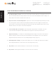
P7 - RS485
1 2 3 4
Input A
Input B
Output A
Output B
Note: Pin 1 will always be
the square pad.