
Instruction Manual

The Sapling Company, Inc.
670 Louis Drive
Warminster, PA 18974
USA
P. (+1) 215.322.6063
F. (+1) 215.322.8498
www.sapling-inc.com
6
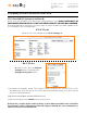
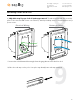
Mounting a Zone Clock Pole
Included in Package
1) Zone Clock Pole
Description
Quantity Picture
2) Mounting Bases
4) Mounting kit
1
2
(Depending on Pole Length)
1
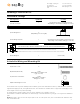
Included in Wiring and Mounting Kit
4a) #6-32x1 screw 8
A user will also have to provide a Phillips-head screwdriver, power and communication cables, a small flat-blade screwdriver,
eight #8 Self-tapping screws, and eight wall anchors. The wall anchors should be able to support the self-tapping screws
and a weight of at least 50 pounds (22.68kg).
IP systems will also require an RJ45 connector, and a crimping tool for an RJ45 connector.
(See below)
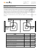
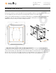
3) Mounting Template 1
4b) #8-32x(SEE NOTE)
4c) Internal-tooth washer
12-42
(Depending on number and
type of clocks)
12-42
(Depending on number
and type of clocks)
The kit will also include the individual clocks and housings. Consult the manual for your type of clock system for additional
parts.
(Shown below. The pole length may vary
depending on the number and type of clocks.)
4d) #10-32x3/8 green screw 1
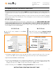
(Shown below. The template content may vary
depending on the number and type of clocks)
M-ZC-60IN-MTGTEMP-1
60.0" [152.40cm]
LEVEL THIS LINE ON THE WALL. SMOOTH OUT THE TEMPLATE AGAINST THE WALL AND TAPE IN PLACE, THEN MARK MOUNTING HOLES.
MARK THE OUTSIDE 4 HOLES TO MOUNT THE METAL PLATE TO THE WALL. USE 4 WALL ANCHORS, EACH RATED AT 50 LBS (22.7 KG).
ONLY WIRED SYSTEMS NEED DOUBLE GANG UTILITY BOXES. IF SO, MARK THE INSIDE 4 HOLES FOR THE EXACT POSITION OF THE UTILITY BOXES, THIS MUST BE ACCURATE.
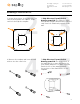
Example:
NOTE: This value is 3/8” for all clocks except square clocks. For each square clock, two screws will be 3/8” while the other
four screws will be 3/4”