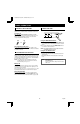
L8QR5/XE (VQC-801P, VQM-801P GB) 1999. 12. 2 VQC-801P VQM-801P INSTRUCTION MANUAL Quad Compressor English GB Quad Compressor Deutsch D Compresseur quadruplex Français F Compresor cuádruple Español E Compressore per quadranti Italiano I About this manual • Before installing and using this unit, please read this manual • carefully. Be sure to keep it handy for later reference. This manual gives basic connections and operating instructions for 2 models (Colour VQC-801P, B/W VQM-801P).
L8QR5/XE (VQC-801P, VQM-801P GB) 1999. 12. 2 PRECAUTION WARNING: TO REDUCE THE RISK OF FIRE OR ELECTRIC SHOCK, DO NOT EXPOSE THIS APPLIANCE TO RAIN OR OTHER MOISTURE. To avoid electrical shock, do not open the cabinet. Refer servicing to qualified personnel only. If the power supply cord (AC power cord) of this appliance is damaged, it must be replaced. Return to a SANYO Authorised Service Centre for replacement of the cord.
L8QR5/XE (VQC-801P, VQM-801P GB) 1999. 12. 2 CONTENTS FEATURES Date/Time function PARTS NAMES . . . . . . . . . . . . . . . . . . . . . . . . . . . . 3 FRONT PANEL . . . . . . . . . . . . . . . . . . . . . . . . . . . . 3 REAR PANEL . . . . . . . . . . . . . . . . . . . . . . . . . . . . . 4 Up to 10 characters title function • Title and time display can be turned on/off • Title and time display position can be selected CONNECTION . . . . . . . . . . . . . . . . . . . . . . . . . . . . .
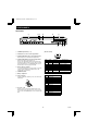
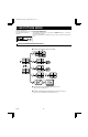
L8QR5/XE (VQC-801P, VQM-801P GB) 1999. 12. 2 PARTS NAMES FRONT PANEL 2 1 3 4 5 6 7 8 9 F ALL RESET POWER 1 2 3 4 5 6 7 8 STILL ZOOM SEQUENCE QUAD LIVE VCR MENU MENU RESET EXIT NEXT G This unit is not equipped with a power switch. The power is turned on/off when the supplied power cord is connected/disconnected at the power source. 1 POWER indicator 7 LIVE button and indicator Press this button to select the live input mode.
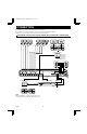
L8QR5/XE (VQC-801P, VQM-801P GB) 1999. 12. 2 PARTS NAMES REAR PANEL 1 1 5 2 CAMERA 6 3 23 7 4 8 VCR IN 4 5 VIDEO OUT QUAD FULL 6 CONTROL QUAD ONLY RC C SW C AL C 1 2 3 4 5 6 7 8 RS232C 7 1 CAMERA input terminals (1 – 8) 8 9 (RS232C terminal) 1 2 3 4 5 2 VCR IN (Video cassette recorder input) terminal 3 VCR OUT QUAD FULL (Video signal output) terminal Output in quad screen and full screen display modes.
L8QR5/XE (VQC-801P, VQM-801P GB) 1999. 12. 2 CONNECTION Before making any connection, make sure all the devices are turned off. Before making the connections, please refer to the instruction manual accompanying each device. If the devices are not connected properly, that may cause a fire and/or damages.
L8QR5/XE (VQC-801P, VQM-801P GB) 1999. 12. 2 CONNECTION REMOTE CONTROLLER CIRCUIT CONNECTIONS Use the layout below to make a remote controller and make the connections to the remote input pins (RC, C) of the CONTROL terminal as indicated. This will permit remote controlled operation of this unit. (make contact LOW input) 1.8kΩ 220Ω SW 1: Camera 1 SW 2: Camera 2 SW 3: Camera 3 SW 4: Camera 4 7.5kΩ 470Ω SW 5: Camera 5 RS232C SW 11 : Camera sequential display SW 12 : Quad screen 4.
L8QR5/XE (VQC-801P, VQM-801P GB) 1999. 12. 2 BASIC OPERATIONS MODE SWITCHING When the unit is connected to a power source, the default display mode will be: live picture from the four cameras 1 – 4 in a quad screen. You can use the VCR, LIVE and MENU buttons to switch to the desired mode (see below for further information). LIVE picture mode VCR playback mode LIVE picture mode Menu mode (LANGUAGE/LANG.
L8QR5/XE (VQC-801P, VQM-801P GB) 1999. 12. 2 BASIC OPERATIONS SECURITY LOCK FUNCTION RESET FUNCTION This function lets you lock the camera live picture mode or VCR playback mode, so that it cannot be switched to another mode. The menus can be reset or cleared. Security lock ALL RESET LIVE Press the LIVE or the VCR button for about 3 seconds. The buzzer will be heard and all the buttons will be locked.
L8QR5/XE (VQC-801P, VQM-801P GB) 1999. 12. 2 LIVE PICTURE MODE (VIDEO OUT QUADFULL) Press the LIVE button. Operations with the monitor connected The live pictures from the cameras connected to the CAMERA terminals (1 – 4) on the unit to the VIDEO OUT QUADFULL back panel will be displayed. terminal. Refer to the diagrams below for the buttons to press in order to select the desired operation mode.
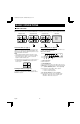
L8QR5/XE (VQC-801P, VQM-801P GB) 1999. 12. 2 QUAD SCREEN OPERATIONS (Live picture) Press the QUAD button once. 01 03 02 05 04 07 QUAD 06 The camera select indicators (1 – 4) light and quad screen A is displayed. Press the QUAD button one more time to switch to quad screen B. 08 NOTE: The quad screen (A or B) last selected is memorised and will be selected first when switching to quad screen mode again.
L8QR5/XE (VQC-801P, VQM-801P GB) 1999. 12. 2 QUAD SCREEN OPERATIONS (Live picture) Example: To freeze the image from camera 4 1 2 STILL 4 ☞ Press the STILL button. The STILL indicator flashes and the still image display mode is selected. Press the camera select 4 button. The camera 4 indicator flashes, the image from camera 4 is frozen, and “S” flashes on-screen. To cancel the still image display mode Press the camera select 4 button one more time, then press the STILL button.
L8QR5/XE (VQC-801P, VQM-801P GB) 1999. 12. 2 QUAD SCREEN OPERATIONS (The zoomed in area is set by the frame position.) 1 2 Example: To zoom in the image from camera 4 and set the zoom range You can select the portion of the image to zoom in. The default zoomed in area is the centre of the image, but if a different zoom range is selected it will be memorized until changed or cancelled.
L8QR5/XE (VQC-801P, VQM-801P GB) 1999. 12. 2 FULL SCREEN OPERATIONS (Live picture) Press a camera select (1 – 8) button. The camera select indicator lights and the live picture from the corresponding camera is displayed full screen. 04 1 2 3 4 5 NOTE: In full screen mode, still and zoomed in image display modes are not possible. 6 7 8 Sequential display of each camera pictures at 1 second interval SEQUENCE Press the SEQUENCE button.
L8QR5/XE (VQC-801P, VQM-801P GB) 1999. 12. 2 VCR PLAYBACK MODE (VIDEO OUT QUADFULL) Operations with the monitor connected to the VIDEO OUT QUADFULL terminal. VIDEO OUT VCR 1 2 3 4 QUAD FULL QUAD ONLY Press the VCR button. The VCR playback mode is selected. When a tape is played back, the recording of the live pictures will be displayed on the monitor. Refer to the diagrams below for the buttons to press in order to select the desired operation mode.
L8QR5/XE (VQC-801P, VQM-801P GB) 1999. 12. 2 MENU SETTING MODE MENUS DISPLAYS To display the menus, press the MENU button. Menu 1 Menu 2 MENU (CLOCK SET) 01-01-2000 SAT 00:00:00 (LANGUAGE/LANG.
L8QR5/XE (VQC-801P, VQM-801P GB) 1999. 12. 2 LANGUAGE SETTING Menu 1 (LANGUAGE/LANG./SPRACHE) The default menu language is English. The available language settings are English, French and German. Setting the language 1 2 3 Press the MENU button once to display the (LANGUAGE/LANG./SPRACHE) menu. Press the l button to highlight the desired language. ☞ Press the MENU button to go to the next menu, or ☞ Press the EXIT button to exit the menu display, the selected language is set.
L8QR5/XE (VQC-801P, VQM-801P GB) 1999. 12. 2 CLOCK AND SUMMER TIME SETTING TO MAKE CHANGES TO THE SETTINGS (CLOCK SET) 1 The default setting is as indicated below. The clock will start after the actual time and date are set and the operations under (SUMMER TIME SET) are completed. Default clock settings: 01:01:2000 SAT 00:00:00 (January 1, 2000 at 00:00) 1 2 3 2 Press the MENU button twice to display the (CLOCK SET) menu.
L8QR5/XE (VQC-801P, VQM-801P GB) 1999. 12. 2 CAMERA TITLE SETTING Menu 3 When a picture from a camera is displayed on-screen the camera number (1 to 8) is displayed at the bottom of the image. You can enter a camera title, such as the camera location (up to 10 characters), that will be displayed instead of the camera number. (TITLE SET) 1 2 3 Press the MENU button 3 times to display the (TITLE SET) menu. 2-1 Example: To set the title “GATE-1F” for the camera 1 and “HALL-2F” for camera 2.
L8QR5/XE (VQC-801P, VQM-801P GB) 1999. 12. 2 ALARM SETTING Menu 4 When an alarm trigger is received from sensors such as a door bell, movement sensor, etc. you can set the display mode and the recording mode for the pictures from the concerned camera. VIDEO OUT (A) (ALARM SET) (ALARM SET) BUZZER ON DURATION 10 S RETRIGGER ON DATA ON VIDEO OUT FULL Changing the Settings 1 2 3 4 Press the MENU button 4 times to display the (ALARM SET) menu.
L8QR5/XE (VQC-801P, VQM-801P GB) 1999. 12. 2 VIDEO SENSOR SETTING Menu 5 You can set an area of the image on the screen to be used as a video sensor ( ). The video sensor detects movement in the selected area of the image and sends an alarm trigger that will initiate priority recording of the images from the concerned camera.
L8QR5/XE (VQC-801P, VQM-801P GB) 1999. 12. 2 TIMER SETTING Menu 6 The timer can be set to record during the daytime and/or nighttime. According to the timer settings, each camera picture full screen display switching speed can be set, and the cameras to be displayed in the quad screens can be selected. (TIMER SET) 1 2 3 Daytime start time (TIMER SET) 00:00 00:00 SEQ. QUAD SEQ.
L8QR5/XE (VQC-801P, VQM-801P GB) 1999. 12. 2 CLOCK, TITLE DISPLAY AND MONITOR SETTINGS DISPLAY SET menu (DISPLAY SET) LIVE CLOCK The clock and the camera title settings entered in the menus (CLOCK SET) and (TITLE SET) can be displayed on-screen. ON: The clock is displayed during live picture mode. OFF: The clock is not displayed during live picture mode.
L8QR5/XE (VQC-801P, VQM-801P GB) 1999. 12.
L8QR5/XE (VQC-801P, VQM-801P GB) 1999. 12.
L8QR5/XE (VQC-801P, VQM-801P GB) 1999. 12. 2 VIDEO LOSS SETTING AND COMPUTER CONTROL SETTING DISPLAY (VIDEO LOSS SET) You can set the display mode when there is an interruption in the video signal feed. FREEZE: When there is video loss, the image just previous to the interruption is frozen on-screen. (Default setting) TEST: When there is video loss, colour bars are displayed on-screen.
L8QR5/XE (VQC-801P, VQM-801P GB) 1999. 12. 2 ALARM DATA DISPLAY SETTING UP THE VCR SIGNAL OUTPUT (SW IN) AUTOMATIC SWITCHING SPEED Menu 9 According to the settings entered in the (ALARM SET), (VIDEO SENSOR SET) and (VIDEO LOSS SET) menus, information about the alarms (alarm data) can be recorded. Up to 100 alarm data entries can be displayed on-screen (on up to 13 screens). 1 (ALARM DATA) 2 Set the VCR recording speed. The settings entered for the SEQ.
L8QR5/XE (VQC-801P, VQM-801P GB) 1999. 12. 2 ALARMS OPERATIONS There are three types of alarms; the alarms set by an external alarm trigger, the alarms set by a loss of the video signal and the alarms set by the video sensor. EXTERNAL ALARMS VIDEO LOSS ALARM When external inputs such as a door bell, an interphone, etc., are connected to the CONTROL terminal (pins 1 – 8), they will send alarm triggers automatically.
L8QR5/XE (VQC-801P, VQM-801P GB) 1999. 12. 2 RS232C CONTROL CONNECTION COMMANDS Connect a 9-pin D-SUB cable (sold separately) from the RS232C terminal on the rear panel to the computer serial connector. COMMANDS AVAILABLE FROM THE COMPUTER 1-8 (90-97) To select the picture from a camera to be displayed full screen. Computer QUAD (83) To display a quad screen. CONTROL RC C SW C AL C 1 2 3 4 5 6 7 8 SEQUENCE (87) In full screen mode, the display will be switched in order, automatically.
L8QR5/XE (VQC-801P, VQM-801P GB) 1999. 12. 2 RS232C CONTROL INFORMATION GATHERING COMMANDS STATUS SENSE(D7) ALARM STATUS SENSE(D5) When this command is sent from the computer, this unit will send a 5-byte response (see Table 1). The external, video loss and video sensor alarm states are indicated by a 6-byte response (see Table 2).
L8QR5/XE (VQC-801P, VQM-801P GB) 1999. 12. 2 RS232C CONTROL COMMANDS AVAILABLE FROM THE QUAD COMPRESSOR ACK(0A) Response when this unit receives a command. NAK(0B) Response if this unit did not receive the command. ALARM(BF) When there is an alarm, this command is sent as header. Then, the alarm information is sent in a 1-byte transmission (see Table 3).
L8QR5/XE (VQC-801P, VQM-801P GB) 1999. 12. 2 RS232C CONTROL COMMAND TABLE (TABLE 4) The commands available are indicated in the table. If a function is not available on the unit, the command will not operate even if sent.
L8QR5/XE (VQC-801P, VQM-801P GB) 1999. 12.
L8QR5/XE (VQC-801P, VQM-801P GB) 1999. 12. 2 SANYO Electric Co., Ltd.