
Operation Manual
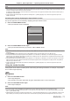

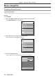
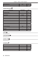
Table Of Contents
- Read this first!
- Chapter 1 Preparation
- Chapter 2 Getting Started
- Chapter 3 Basic Operations
- Switching on/off the projector
- Projecting
- Operating with the remote control
- Switching the input
- Using the shutter function
- Using the on-screen display function
- Using the automatic setup function
- Switching the image aspect ratio
- Using the function button
- Displaying internal test pattern
- Using the status function
- Using the AC voltage monitor function
- Setting ID number of the remote control
- Chapter 4 Settings
- Menu navigation
- [PICTURE] menu
- [POSITION] menu
- [ADVANCED MENU] menu
- [DISPLAY LANGUAGE] menu
- [3D SETTINGS] menu
- [DISPLAY OPTION] menu
- [COLOR MATCHING]
- [LARGE SCREEN CORRECTION]
- [SCREEN SETTING]
- [AUTO SIGNAL]
- [AUTO SETUP]
- [BACKUP INPUT SETTING]
- [SIMUL INPUT SETTING]
- [RGB IN]
- [DVI-D IN]
- [HDMI IN]
- [DIGITAL LINK IN]
- [SDI IN]
- [ON-SCREEN DISPLAY]
- [IMAGE ROTATION]
- [BACK COLOR]
- [STARTUP LOGO]
- [UNIFORMITY]
- [SHUTTER SETTING]
- [FREEZE]
- [WAVEFORM MONITOR]
- [CUT OFF]
- [PROJECTOR SETUP] menu
- [PROJECTOR ID]
- [PROJECTION METHOD]
- [OPERATION SETTING]
- [LIGHT OUTPUT]
- [BRIGHTNESS CONTROL]
- [STANDBY MODE]
- [NO SIGNAL SHUT-OFF]
- [NO SIGNAL LIGHTS-OUT]
- [INITIAL STARTUP]
- [STARTUP INPUT SELECT]
- [DATE AND TIME]
- [SCHEDULE]
- [RS-232C]
- [REMOTE2 MODE]
- [FUNCTION BUTTON]
- [LENS CALIBRATION]
- [LENS MEMORY]
- [STATUS]
- [AC VOLTAGE MONITOR]
- [SAVE ALL USER DATA]
- [LOAD ALL USER DATA]
- [INITIALIZE]
- [SERVICE PASSWORD]
- [P IN P] menu
- [TEST PATTERN] menu
- [SIGNAL LIST] menu
- [SECURITY] menu
- [NETWORK] menu
- Chapter 5 Maintenance
- Chapter 6 Appendix
Chapter 3 Basic Operations — Operating with the remote control
ENGLISH - 71
Note
f When the optional DIGITAL LINK output supported device (Model No.: ET-YFB100G, ET-YFB200G) is connected to the <DIGITAL LINK/
LAN> terminal, the input on the DIGITAL LINK output supported device changes each time the <DIGITAL LINK> button is pressed. The input
can also be changed using the RS-232C control command.
For twisted-pair-cable transmitters of other manufacturers, switch the input on the projector to DIGITAL LINK, and then switch the input on
the twisted-pair-cable transmitter.
f Congure [RGB1 INPUT SETTING] of the [DISPLAY OPTION] menu → [RGB IN] (x page 112) to match the signal to be input to the
<RGB 1 IN> terminal.
Switching the input by displaying the input selection screen
The input for projection can be selected by displaying the input selection screen.
1) Press the <INPUT MENU> button.
f The input selection screen is displayed.
INPUT SELECT
RGB1
RGB2
DVI-D
HDMI
DIGITAL LINK
SDI1
SDI2
SELECT
SET
ENTER
2) Press the <INPUT MENU> button again.
f The input will switch each time you press the <INPUT MENU> button.
Note
f Input can be switched by selecting the input to project by pressing as and pressing the <ENTER> button while the input selection screen
is displayed.
f The [P IN P MODE] screen is displayed when the <INPUT MENU> button is pressed while in the P IN P. (x page 146)
f If the optional DIGITAL LINK output supported device (Model No.: ET-YFB100G, ET-YFB200G) is connected to the projector, the input
selection menu for the DIGITAL LINK output supported device is displayed when the <ENTER> button is pressed while the DIGITAL LINK
input is selected in the input selection screen.
f If the optional DIGITAL LINK output supported device (Model No.: ET-YFB100G, ET-YFB200G) is connected to the projector, the DIGITAL
LINK logo and the input name selected in the DIGITAL LINK output supported device are displayed in the display section of the [DIGITAL
LINK] in the input selection screen.
f Congure [RGB1 INPUT SETTING] of the [DISPLAY OPTION] menu → [RGB IN] (x page 112) to match the signal to be input to the
<RGB 1 IN> terminal.
Using the shutter function
If the projector is not used for a certain period of time during the meeting intermission, for example, it is possible
to turn off the image temporarily.
button
1) Press the <SHUTTER> button.
f The image disappears.
f This operation can be also performed using the <SHUTTER> button on the control panel.
2) Press the <SHUTTER> button again.
f The image is displayed.
Note
f The power indicator <ON (G)/STANDBY (R)> will blink slowly in green while the shutter function is in use (shutter: closed).
f You can set whether to use the mechanical shutter or not and the time for the fade in/fade out of the image using the [DISPLAY OPTION]
menu → [SHUTTER SETTING].
f If [MECHANICAL SHUTTER] in the [DISPLAY OPTION] menu → [SHUTTER SETTING] (x page 121) is set to [DISABLE], the light source
may be lit dimly due to warm-up when the shutter function is used while the operating environment temperature is around 0 °C (32 °F).