
Operation Manual
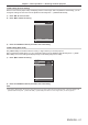
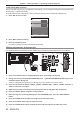
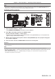
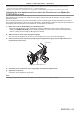
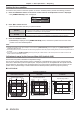
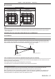
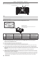
Table Of Contents
- Read this first!
- Chapter 1 Preparation
- Chapter 2 Getting Started
- Chapter 3 Basic Operations
- Switching on/off the projector
- Projecting
- Operating with the remote control
- Switching the input
- Using the shutter function
- Using the on-screen display function
- Using the automatic setup function
- Switching the image aspect ratio
- Using the function button
- Displaying internal test pattern
- Using the status function
- Using the AC voltage monitor function
- Setting ID number of the remote control
- Chapter 4 Settings
- Menu navigation
- [PICTURE] menu
- [POSITION] menu
- [ADVANCED MENU] menu
- [DISPLAY LANGUAGE] menu
- [3D SETTINGS] menu
- [DISPLAY OPTION] menu
- [COLOR MATCHING]
- [LARGE SCREEN CORRECTION]
- [SCREEN SETTING]
- [AUTO SIGNAL]
- [AUTO SETUP]
- [BACKUP INPUT SETTING]
- [SIMUL INPUT SETTING]
- [RGB IN]
- [DVI-D IN]
- [HDMI IN]
- [DIGITAL LINK IN]
- [SDI IN]
- [ON-SCREEN DISPLAY]
- [IMAGE ROTATION]
- [BACK COLOR]
- [STARTUP LOGO]
- [UNIFORMITY]
- [SHUTTER SETTING]
- [FREEZE]
- [WAVEFORM MONITOR]
- [CUT OFF]
- [PROJECTOR SETUP] menu
- [PROJECTOR ID]
- [PROJECTION METHOD]
- [OPERATION SETTING]
- [LIGHT OUTPUT]
- [BRIGHTNESS CONTROL]
- [STANDBY MODE]
- [NO SIGNAL SHUT-OFF]
- [NO SIGNAL LIGHTS-OUT]
- [INITIAL STARTUP]
- [STARTUP INPUT SELECT]
- [DATE AND TIME]
- [SCHEDULE]
- [RS-232C]
- [REMOTE2 MODE]
- [FUNCTION BUTTON]
- [LENS CALIBRATION]
- [LENS MEMORY]
- [STATUS]
- [AC VOLTAGE MONITOR]
- [SAVE ALL USER DATA]
- [LOAD ALL USER DATA]
- [INITIALIZE]
- [SERVICE PASSWORD]
- [P IN P] menu
- [TEST PATTERN] menu
- [SIGNAL LIST] menu
- [SECURITY] menu
- [NETWORK] menu
- Chapter 5 Maintenance
- Chapter 6 Appendix
Chapter 3 Basic Operations — Projecting
68 - ENGLISH
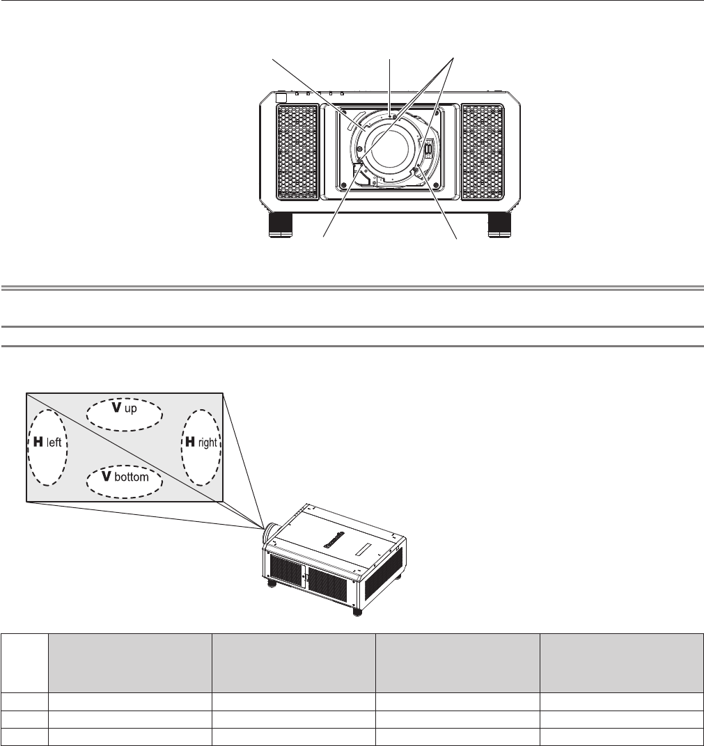
r Front view diagram of the lens mounter (viewed from the screen side)
(a)
(b) (c)
Lens mount bracket
Fixing screws
Note
f Focus adjustment screws (a), (b), and (c) are adjusted with the lens attached.
Adjustment procedure
r Relationship between the adjustment location and adjustment screws
(b) (c)
(b)+(c)
(a)
Adjustment location:
Location where the just focus point of the screen is in the
inner side of the screen
When the just focus point of
the screen in V up (top in the
vertical direction) is in the inner
side of the screen
When the just focus point of the
screen in V bottom (bottom in
the vertical direction) is in the
inner side of the screen
When the just focus point of
the screen in H left (left in the
horizontal direction) is in the
inner side of the screen
When the just focus point of the
screen in H right (right in the
horizontal direction) is in the
inner side of the screen
(a) Rotate counterclockwise ― ― ―
(b) ― Rotate counterclockwise Rotate counterclockwise ―
(c) ― Rotate counterclockwise ― Rotate counterclockwise
1) Press the <FOCUS> button on the remote control or the <LENS> button on the control panel to
display the focus adjustment screen.
2) Press s to shift the focus of the entire screen once.
3) Press a to stop on any part of the screen to be the first just focus point.
f For the location where focus is shifted in this state, the just focus point is on the inner side of the screen.
4) Loosen the fixed screws in the position relative to the location where the focus is shifted the most
(the location where the just focus point is shifted the most towards the inner side in Step 2)) up to two
rotations.
f Turn screws clockwise in two locations, or at least in one location when making an adjustment.
5) Slowly turn the focus adjustment screws corresponding to the locations counterclockwise and stop
where the image is in focus. (x page 67)
f If the screws are turned counterclockwise, the tilt of the lens will change by moving the lens mount bracket
of the lens mounter forward (screen side), and in the projected image on the screen, the focus point in the
opposite direction of the adjustment screws will move from the inner side of the screen to the outside.