
Operation Manual
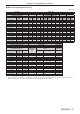
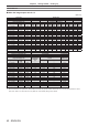
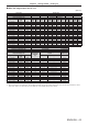
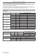
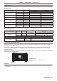
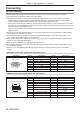
Table Of Contents
- Read this first!
- Chapter 1 Preparation
- Chapter 2 Getting Started
- Chapter 3 Basic Operations
- Switching on/off the projector
- Projecting
- Operating with the remote control
- Switching the input
- Using the shutter function
- Using the on-screen display function
- Using the automatic setup function
- Switching the image aspect ratio
- Using the function button
- Displaying internal test pattern
- Using the status function
- Using the AC voltage monitor function
- Setting ID number of the remote control
- Chapter 4 Settings
- Menu navigation
- [PICTURE] menu
- [POSITION] menu
- [ADVANCED MENU] menu
- [DISPLAY LANGUAGE] menu
- [3D SETTINGS] menu
- [DISPLAY OPTION] menu
- [COLOR MATCHING]
- [LARGE SCREEN CORRECTION]
- [SCREEN SETTING]
- [AUTO SIGNAL]
- [AUTO SETUP]
- [BACKUP INPUT SETTING]
- [SIMUL INPUT SETTING]
- [RGB IN]
- [DVI-D IN]
- [HDMI IN]
- [DIGITAL LINK IN]
- [SDI IN]
- [ON-SCREEN DISPLAY]
- [IMAGE ROTATION]
- [BACK COLOR]
- [STARTUP LOGO]
- [UNIFORMITY]
- [SHUTTER SETTING]
- [FREEZE]
- [WAVEFORM MONITOR]
- [CUT OFF]
- [PROJECTOR SETUP] menu
- [PROJECTOR ID]
- [PROJECTION METHOD]
- [OPERATION SETTING]
- [LIGHT OUTPUT]
- [BRIGHTNESS CONTROL]
- [STANDBY MODE]
- [NO SIGNAL SHUT-OFF]
- [NO SIGNAL LIGHTS-OUT]
- [INITIAL STARTUP]
- [STARTUP INPUT SELECT]
- [DATE AND TIME]
- [SCHEDULE]
- [RS-232C]
- [REMOTE2 MODE]
- [FUNCTION BUTTON]
- [LENS CALIBRATION]
- [LENS MEMORY]
- [STATUS]
- [AC VOLTAGE MONITOR]
- [SAVE ALL USER DATA]
- [LOAD ALL USER DATA]
- [INITIALIZE]
- [SERVICE PASSWORD]
- [P IN P] menu
- [TEST PATTERN] menu
- [SIGNAL LIST] menu
- [SECURITY] menu
- [NETWORK] menu
- Chapter 5 Maintenance
- Chapter 6 Appendix
Chapter 2 Getting Started — Connecting
ENGLISH - 49
<DVI-D IN> terminal pin assignments and signal names
Outside view Pin No. Signal name Pin No. Signal name
(17)(24)
(16)
(9)
(1)(8)
(1) T.M.D.S data 2
-
(13) ―
(2) T.M.D.S data 2+ (14) +5 V
(3) T.M.D.S data 2/4 shield (15) GND
(4) ― (16) Hot plug detection
(5) ― (17) T.M.D.S data 0
-
(6) DDC clock (18) T.M.D.S data 0+
(7) DDC data (19) T.M.D.S data 0/5 shield
(8) ― (20) ―
(9) T.M.D.S data 1
-
(21) ―
(10) T.M.D.S data 1+ (22) T.M.D.S clock shield
(11) T.M.D.S data 1/3 shield (23) T.M.D.S clock+
(12) ― (24) T.M.D.S clock
-
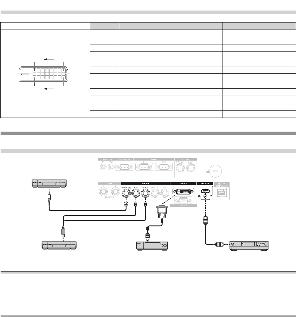
Connecting example: AV equipment
For <HDMI IN>/<DVI-D IN>/<RGB 1 IN> terminals
Blu-ray disc playerVCR (with built-in TBC)
VCR (with built-in TBC)
DVD player with HDMI terminal (HDCP)
Attention
f Always use one of the following when connecting a VCR.
g A VCR with built-in time base corrector (TBC)
g A time base corrector (TBC) between the projector and the VCR
f If nonstandard burst signals are connected, the image may be distorted. In such a case, connect the time base corrector (TBC) between the
projector and the external devices.
Note
f When entering DVI-D, it may be necessary to switch the setting using the [DISPLAY OPTION] menu → [DVI-D IN] → [EDID SELECT]
depending on the external device to be connected.
f The <DVI-D IN> terminal can be connected to HDMI- or DVI-D-compliant devices. However, images may not appear or may not be
displayed properly on some devices.
f For the HDMI cable, use an HDMI High Speed cable that conforms to the HDMI standards. If a cable that does not conform to the HDMI
standards is used, images may be interrupted or may not be displayed.
f The <HDMI IN> terminal of the projector can be connected to an external device equipped with a DVI-D terminal using an HDMI/DVI
conversion cable. However, this may not function properly for some external devices, and images may not be displayed.
f The projector does not support VIERA Link (HDMI).
f When the video signal and the Y/C signal are input, switch the setting using the [DISPLAY OPTION] menu → [RGB IN] → [RGB1 INPUT
SETTING] (x page 112).