
Operation Manual
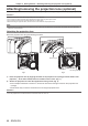
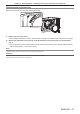
Table Of Contents
- Read this first!
- Chapter 1 Preparation
- Chapter 2 Getting Started
- Chapter 3 Basic Operations
- Switching on/off the projector
- Projecting
- Operating with the remote control
- Switching the input
- Using the shutter function
- Using the on-screen display function
- Using the automatic setup function
- Switching the image aspect ratio
- Using the function button
- Displaying internal test pattern
- Using the status function
- Using the AC voltage monitor function
- Setting ID number of the remote control
- Chapter 4 Settings
- Menu navigation
- [PICTURE] menu
- [POSITION] menu
- [ADVANCED MENU] menu
- [DISPLAY LANGUAGE] menu
- [3D SETTINGS] menu
- [DISPLAY OPTION] menu
- [COLOR MATCHING]
- [LARGE SCREEN CORRECTION]
- [SCREEN SETTING]
- [AUTO SIGNAL]
- [AUTO SETUP]
- [BACKUP INPUT SETTING]
- [SIMUL INPUT SETTING]
- [RGB IN]
- [DVI-D IN]
- [HDMI IN]
- [DIGITAL LINK IN]
- [SDI IN]
- [ON-SCREEN DISPLAY]
- [IMAGE ROTATION]
- [BACK COLOR]
- [STARTUP LOGO]
- [UNIFORMITY]
- [SHUTTER SETTING]
- [FREEZE]
- [WAVEFORM MONITOR]
- [CUT OFF]
- [PROJECTOR SETUP] menu
- [PROJECTOR ID]
- [PROJECTION METHOD]
- [OPERATION SETTING]
- [LIGHT OUTPUT]
- [BRIGHTNESS CONTROL]
- [STANDBY MODE]
- [NO SIGNAL SHUT-OFF]
- [NO SIGNAL LIGHTS-OUT]
- [INITIAL STARTUP]
- [STARTUP INPUT SELECT]
- [DATE AND TIME]
- [SCHEDULE]
- [RS-232C]
- [REMOTE2 MODE]
- [FUNCTION BUTTON]
- [LENS CALIBRATION]
- [LENS MEMORY]
- [STATUS]
- [AC VOLTAGE MONITOR]
- [SAVE ALL USER DATA]
- [LOAD ALL USER DATA]
- [INITIALIZE]
- [SERVICE PASSWORD]
- [P IN P] menu
- [TEST PATTERN] menu
- [SIGNAL LIST] menu
- [SECURITY] menu
- [NETWORK] menu
- Chapter 5 Maintenance
- Chapter 6 Appendix
Chapter 2 Getting Started — Attaching/removing the projection lens (optional)
46 - ENGLISH
Attaching/removing the projection lens (optional)
Move the lens position to the home position before replacing or removing the projection lens. (x page 66)
Attention
f Replace the projection lens after turning off the power of the projector.
f Do not touch the electric contacts of the projection lens. Dust or dirt may cause poor contact.
f Do not touch the surface of the projection lens with your bare hands.
f Before attaching the projection lens, remove the lens cover attached to the projection lens.
Note
f The precautions for handling the lens are different for the Fixed-focus Lens (Model No.: ET-D75LE90). For details, refer to the Operating
Instructions of ET-D75LE90.
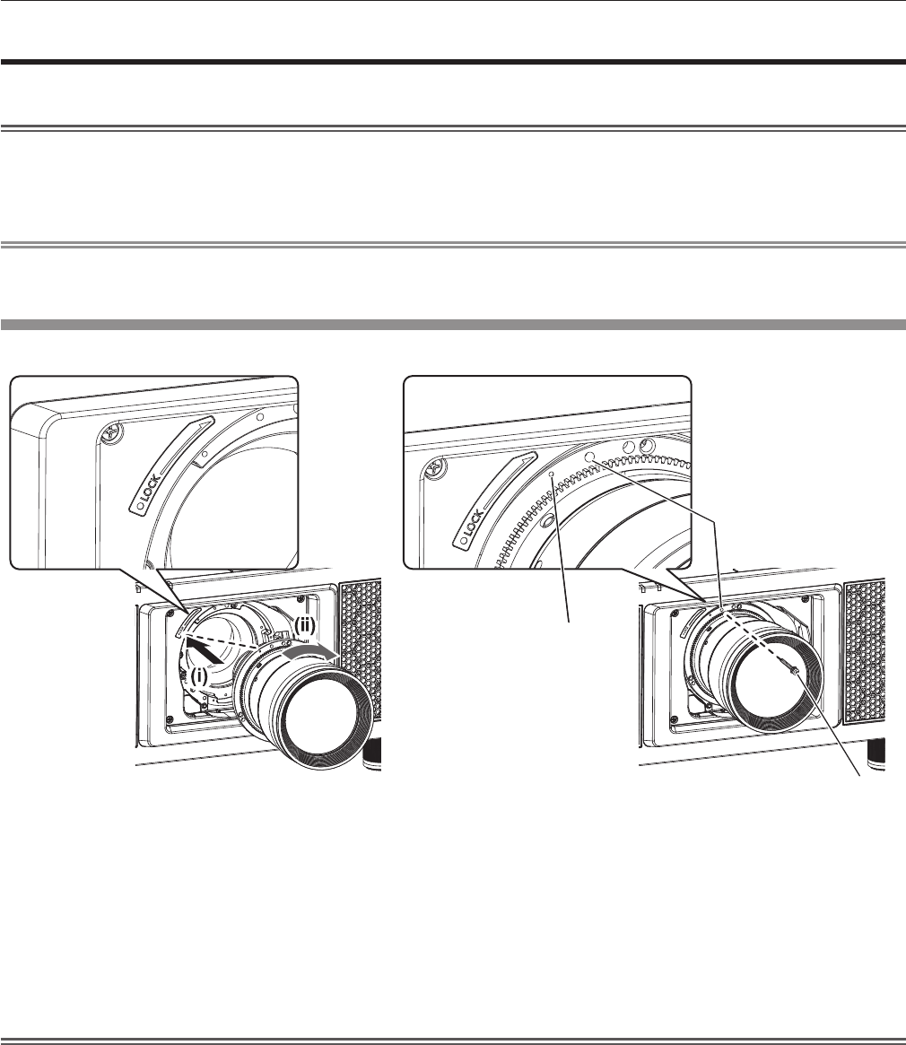
Attaching the projection lens
Attach the projection lens using the following procedure.
Mark (orange)
Fig. 1 Fig. 2
Screw hole A
Lens fixing screw
1) Insert the projection lens by aligning the mark on the projection lens (orange) with the mark on the
projector (E to the left of LOCK) and turn clockwise until it clicks. (Fig. 1)
2) Secure the projection lens with the supplied lens fixing screw. (Fig. 2)
f Use a Phillips screwdriver to secure it in screw hole A located to the right of mark on the projection lens
(orange).
f Some lenses may not have a screw hole A for securing the projection lens.
Attention
f Turn the projection lens counterclockwise to conrm that it does not come out.