
Operation Manual
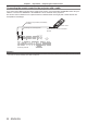

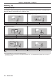
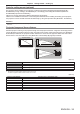
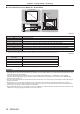
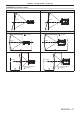
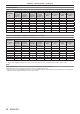
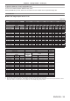
Table Of Contents
- Read this first!
- Chapter 1 Preparation
- Chapter 2 Getting Started
- Chapter 3 Basic Operations
- Switching on/off the projector
- Projecting
- Operating with the remote control
- Switching the input
- Using the shutter function
- Using the on-screen display function
- Using the automatic setup function
- Switching the image aspect ratio
- Using the function button
- Displaying internal test pattern
- Using the status function
- Using the AC voltage monitor function
- Setting ID number of the remote control
- Chapter 4 Settings
- Menu navigation
- [PICTURE] menu
- [POSITION] menu
- [ADVANCED MENU] menu
- [DISPLAY LANGUAGE] menu
- [3D SETTINGS] menu
- [DISPLAY OPTION] menu
- [COLOR MATCHING]
- [LARGE SCREEN CORRECTION]
- [SCREEN SETTING]
- [AUTO SIGNAL]
- [AUTO SETUP]
- [BACKUP INPUT SETTING]
- [SIMUL INPUT SETTING]
- [RGB IN]
- [DVI-D IN]
- [HDMI IN]
- [DIGITAL LINK IN]
- [SDI IN]
- [ON-SCREEN DISPLAY]
- [IMAGE ROTATION]
- [BACK COLOR]
- [STARTUP LOGO]
- [UNIFORMITY]
- [SHUTTER SETTING]
- [FREEZE]
- [WAVEFORM MONITOR]
- [CUT OFF]
- [PROJECTOR SETUP] menu
- [PROJECTOR ID]
- [PROJECTION METHOD]
- [OPERATION SETTING]
- [LIGHT OUTPUT]
- [BRIGHTNESS CONTROL]
- [STANDBY MODE]
- [NO SIGNAL SHUT-OFF]
- [NO SIGNAL LIGHTS-OUT]
- [INITIAL STARTUP]
- [STARTUP INPUT SELECT]
- [DATE AND TIME]
- [SCHEDULE]
- [RS-232C]
- [REMOTE2 MODE]
- [FUNCTION BUTTON]
- [LENS CALIBRATION]
- [LENS MEMORY]
- [STATUS]
- [AC VOLTAGE MONITOR]
- [SAVE ALL USER DATA]
- [LOAD ALL USER DATA]
- [INITIALIZE]
- [SERVICE PASSWORD]
- [P IN P] menu
- [TEST PATTERN] menu
- [SIGNAL LIST] menu
- [SECURITY] menu
- [NETWORK] menu
- Chapter 5 Maintenance
- Chapter 6 Appendix
Chapter 2 Getting Started — Setting up
ENGLISH - 35
Parts for ceiling mount (optional)
The projector can be installed on the ceiling by combining the optional Ceiling Mount Bracket (Model No.:
ET-PKD520H (for High Ceilings), ET-PKD520S (for Low Ceilings)) and Ceiling Mount Bracket (Model No.:
ET-PKD520B (Projector Mount Bracket)).
f Be sure to use the Ceiling Mount Bracket specied for this projector.
f Refer to the Installation Instructions of the Ceiling Mount Bracket when installing and setting up the projector.
Two projectors can be stacked and used simultaneously by using the optional Frame (Model No.: ET-PFD510).
Attention
f To ensure projector performance and security, installation of the Ceiling Mount Bracket must be carried out by your dealer or a qualied
technician.
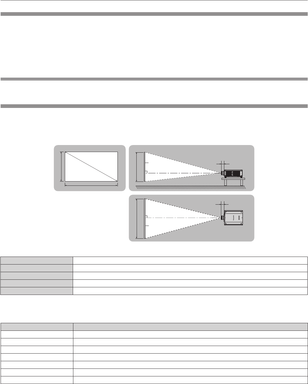
Projected image and throw distance
Install the projector referring to the projected image size and projection distance. Image size and image position
can be adjusted in accordance with the screen size and screen position. When the Fixed-focus Lens (Model No.:
ET-D75LE90) is attached, the projection relation between the screen and the projector differs from that of other
lenses. Refer to “For the Fixed-focus Lens (Model No.: ET-D75LE90)” (x page 36) for details.
SD
L (LW/LT)
L1
L1
L (LW/LT)
SW SH
SH
SW
Projected image
Screen
Screen
(Unit: m)
L (LW/LT)
*1
Projection distance
L1 Lens protrusion dimension
SH Projected image height
SW Projected image width
SD Projected image size
*1 LW: Minimum projection distance when the Zoom Lens is used
LT: Maximum projection distance when the Zoom Lens is used
(Unit: m)
Projection lens Model No. Dimension for L1 (approximate value)
ET-D75LE6 0.212
ET-D75LE8 0.254
ET-D75LE10 0.125
ET-D75LE20 0.121
ET-D75LE30 0.121
ET-D75LE40 0.124
ET-D75LE50 0.203