
Operation Manual
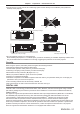
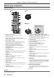

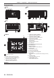
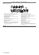
Table Of Contents
- Read this first!
- Chapter 1 Preparation
- Chapter 2 Getting Started
- Chapter 3 Basic Operations
- Switching on/off the projector
- Projecting
- Operating with the remote control
- Switching the input
- Using the shutter function
- Using the on-screen display function
- Using the automatic setup function
- Switching the image aspect ratio
- Using the function button
- Displaying internal test pattern
- Using the status function
- Using the AC voltage monitor function
- Setting ID number of the remote control
- Chapter 4 Settings
- Menu navigation
- [PICTURE] menu
- [POSITION] menu
- [ADVANCED MENU] menu
- [DISPLAY LANGUAGE] menu
- [3D SETTINGS] menu
- [DISPLAY OPTION] menu
- [COLOR MATCHING]
- [LARGE SCREEN CORRECTION]
- [SCREEN SETTING]
- [AUTO SIGNAL]
- [AUTO SETUP]
- [BACKUP INPUT SETTING]
- [SIMUL INPUT SETTING]
- [RGB IN]
- [DVI-D IN]
- [HDMI IN]
- [DIGITAL LINK IN]
- [SDI IN]
- [ON-SCREEN DISPLAY]
- [IMAGE ROTATION]
- [BACK COLOR]
- [STARTUP LOGO]
- [UNIFORMITY]
- [SHUTTER SETTING]
- [FREEZE]
- [WAVEFORM MONITOR]
- [CUT OFF]
- [PROJECTOR SETUP] menu
- [PROJECTOR ID]
- [PROJECTION METHOD]
- [OPERATION SETTING]
- [LIGHT OUTPUT]
- [BRIGHTNESS CONTROL]
- [STANDBY MODE]
- [NO SIGNAL SHUT-OFF]
- [NO SIGNAL LIGHTS-OUT]
- [INITIAL STARTUP]
- [STARTUP INPUT SELECT]
- [DATE AND TIME]
- [SCHEDULE]
- [RS-232C]
- [REMOTE2 MODE]
- [FUNCTION BUTTON]
- [LENS CALIBRATION]
- [LENS MEMORY]
- [STATUS]
- [AC VOLTAGE MONITOR]
- [SAVE ALL USER DATA]
- [LOAD ALL USER DATA]
- [INITIALIZE]
- [SERVICE PASSWORD]
- [P IN P] menu
- [TEST PATTERN] menu
- [SIGNAL LIST] menu
- [SECURITY] menu
- [NETWORK] menu
- Chapter 5 Maintenance
- Chapter 6 Appendix
Chapter 1 Preparation — About your projector
28 - ENGLISH
Projector body
1 2 3
4
5 6
7 7
9
8
88 12
16 17
13 14
10
15
Front
Side
Rear
11
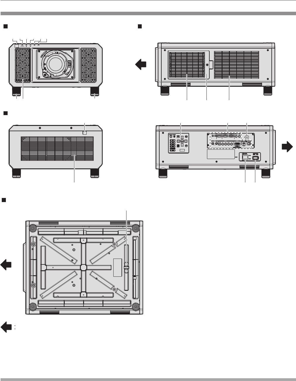
Projection direction
Bottom
1 Remote control signal receiver (front)
2 Power indicator <ON (G)/STANDBY (R)>
Indicates the status of the power.
3 Light source indicator <LIGHT1>
Indicates the status of light source 1.
4 Light source indicator <LIGHT2>
Indicates the status of light source 2.
5 Temperature indicator <TEMP>
Indicates the internal temperature status.
6 Filter indicator <FILTER>
Indicates the status of the air lter unit.
7 Adjustable feet
Adjusts the projection angle.
8 Air intake port
9 Remote control signal receiver (rear)
10 Air exhaust port
11 Burglar hook port
Attaches a burglar prevention cable, etc.
12 Air lter cover
The air lter unit is inside.
13 Control panel (x page 29)
14 Connecting terminals (x page 30)
15 Security slot
This security slot is compatible with the Kensington security
cables.
16 <AC IN> terminal
Connect the supplied power cord.
17 <MAIN POWER> switch
Turns on/off the main power.
Attention
f Do not block the ventilation ports (intake and exhaust) of the projector.