
Operation Manual
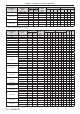
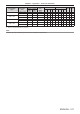


Table Of Contents
- Read this first!
- Chapter 1 Preparation
- Chapter 2 Getting Started
- Chapter 3 Basic Operations
- Switching on/off the projector
- Projecting
- Operating with the remote control
- Switching the input
- Using the shutter function
- Using the on-screen display function
- Using the automatic setup function
- Switching the image aspect ratio
- Using the function button
- Displaying internal test pattern
- Using the status function
- Using the AC voltage monitor function
- Setting ID number of the remote control
- Chapter 4 Settings
- Menu navigation
- [PICTURE] menu
- [POSITION] menu
- [ADVANCED MENU] menu
- [DISPLAY LANGUAGE] menu
- [3D SETTINGS] menu
- [DISPLAY OPTION] menu
- [COLOR MATCHING]
- [LARGE SCREEN CORRECTION]
- [SCREEN SETTING]
- [AUTO SIGNAL]
- [AUTO SETUP]
- [BACKUP INPUT SETTING]
- [SIMUL INPUT SETTING]
- [RGB IN]
- [DVI-D IN]
- [HDMI IN]
- [DIGITAL LINK IN]
- [SDI IN]
- [ON-SCREEN DISPLAY]
- [IMAGE ROTATION]
- [BACK COLOR]
- [STARTUP LOGO]
- [UNIFORMITY]
- [SHUTTER SETTING]
- [FREEZE]
- [WAVEFORM MONITOR]
- [CUT OFF]
- [PROJECTOR SETUP] menu
- [PROJECTOR ID]
- [PROJECTION METHOD]
- [OPERATION SETTING]
- [LIGHT OUTPUT]
- [BRIGHTNESS CONTROL]
- [STANDBY MODE]
- [NO SIGNAL SHUT-OFF]
- [NO SIGNAL LIGHTS-OUT]
- [INITIAL STARTUP]
- [STARTUP INPUT SELECT]
- [DATE AND TIME]
- [SCHEDULE]
- [RS-232C]
- [REMOTE2 MODE]
- [FUNCTION BUTTON]
- [LENS CALIBRATION]
- [LENS MEMORY]
- [STATUS]
- [AC VOLTAGE MONITOR]
- [SAVE ALL USER DATA]
- [LOAD ALL USER DATA]
- [INITIALIZE]
- [SERVICE PASSWORD]
- [P IN P] menu
- [TEST PATTERN] menu
- [SIGNAL LIST] menu
- [SECURITY] menu
- [NETWORK] menu
- Chapter 5 Maintenance
- Chapter 6 Appendix

Chapter 6 Appendix — Specications
214 - ENGLISH
r Terminal
<RGB 1 IN> terminal
1 set (BNC x 5 (RGB/YP
B
P
R
/YC
B
C
R
/YC/VIDEO x 1))
RGB signal 0.7 V [p-p] 75 Ω (SYNC ON GREEN: 1.0 V [p-p] 75 Ω)
SYNC/HD TTL high impedance, automatic positive/negative
polarity compatible
VD TTL high impedance, automatic positive/negative
polarity compatible
YP
B
P
R
signal Y: 1.0 V [p-p] including synchronization signal, P
B
P
R
: 0.7 V [p-p] 75 Ω
Y/C signal Y: 1.0 V [p-p], C: 0.286 V [p-p] 75 Ω
VIDEO signal 1.0 V [p-p] 75 Ω
<RGB 2 IN> terminal
1 set, high-density D-Sub 15 p (female)
RGB signal 0.7 V [p-p] 75 Ω (SYNC ON GREEN: 1.0 V [p-p] 75 Ω)
SYNC/HD TTL high impedance, automatic positive/negative
polarity compatible
VD TTL high impedance, automatic positive/negative
polarity compatible
YP
B
P
R
signal Y: 1.0 V [p-p] including synchronization signal, P
B
P
R
: 0.7 V [p-p] 75 Ω
<DVI-D IN> terminal 1 set, DVI-D 24 p, single link, DVI 1.0 compliant, HDCP compatible
<HDMI IN> terminal 1 set, HDMI 19 p, HDCP compatible, Deep Color compatible
<SDI IN 1> terminal
1 set (BNC)
SD-SDI signal SMPTE ST 259 compliant
HD-SDI signal SMPTE ST 292 compliant
3G-SDI signal SMPTE ST 424 compliant
Dual link HD-SDI
(LINK-A) signal
SMPTE ST 372 compliant
Dual link 3G-SDI (Link
1) signal
SMPTE ST 425 compliant
<SDI IN 2> terminal
1 set (BNC)
SD-SDI signal SMPTE ST 259 compliant
HD-SDI signal SMPTE ST 292 compliant
3G-SDI signal SMPTE ST 424 compliant
Dual link HD-SDI
(LINK-B) signal
SMPTE ST 372 compliant
Dual link 3G-SDI (Link
2) signal
SMPTE ST 425 compliant
<3D SYNC 1 IN/OUT> terminal
1 set (BNC)
During input setting TTL high impedance
During output setting TTL output: Maximum 10 mA
<3D SYNC 2 OUT> terminal
1 set (BNC)
TTL output: Maximum 10 mA
<SERIAL IN>/ <SERIAL OUT>
terminal
D-Sub 9 p, 1 set each, RS-232C compliant, for computer control
<REMOTE 1 IN>/ <REMOTE 1
OUT> terminal
M3 stereo mini jack, 1 set each, for remote control (wired)/for projector connection control
<REMOTE 2 IN> terminal 1 set, D-Sub 9 p, for contact control
<DIGITAL LINK/LAN> terminal
1 set, RJ-45, for network and DIGITAL LINK connections (HDBaseT
TM
compliant), PJLink compatible,
100Base-TX, Art-Net compatible, HDCP compatible, Deep Color compatible
Note
f The model numbers of accessories and optional accessories are subject to change without prior notice.