
Operation Manual
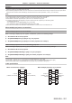
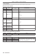
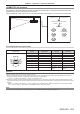
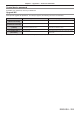
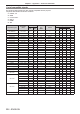
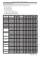
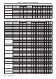
Table Of Contents
- Read this first!
- Chapter 1 Preparation
- Chapter 2 Getting Started
- Chapter 3 Basic Operations
- Switching on/off the projector
- Projecting
- Operating with the remote control
- Switching the input
- Using the shutter function
- Using the on-screen display function
- Using the automatic setup function
- Switching the image aspect ratio
- Using the function button
- Displaying internal test pattern
- Using the status function
- Using the AC voltage monitor function
- Setting ID number of the remote control
- Chapter 4 Settings
- Menu navigation
- [PICTURE] menu
- [POSITION] menu
- [ADVANCED MENU] menu
- [DISPLAY LANGUAGE] menu
- [3D SETTINGS] menu
- [DISPLAY OPTION] menu
- [COLOR MATCHING]
- [LARGE SCREEN CORRECTION]
- [SCREEN SETTING]
- [AUTO SIGNAL]
- [AUTO SETUP]
- [BACKUP INPUT SETTING]
- [SIMUL INPUT SETTING]
- [RGB IN]
- [DVI-D IN]
- [HDMI IN]
- [DIGITAL LINK IN]
- [SDI IN]
- [ON-SCREEN DISPLAY]
- [IMAGE ROTATION]
- [BACK COLOR]
- [STARTUP LOGO]
- [UNIFORMITY]
- [SHUTTER SETTING]
- [FREEZE]
- [WAVEFORM MONITOR]
- [CUT OFF]
- [PROJECTOR SETUP] menu
- [PROJECTOR ID]
- [PROJECTION METHOD]
- [OPERATION SETTING]
- [LIGHT OUTPUT]
- [BRIGHTNESS CONTROL]
- [STANDBY MODE]
- [NO SIGNAL SHUT-OFF]
- [NO SIGNAL LIGHTS-OUT]
- [INITIAL STARTUP]
- [STARTUP INPUT SELECT]
- [DATE AND TIME]
- [SCHEDULE]
- [RS-232C]
- [REMOTE2 MODE]
- [FUNCTION BUTTON]
- [LENS CALIBRATION]
- [LENS MEMORY]
- [STATUS]
- [AC VOLTAGE MONITOR]
- [SAVE ALL USER DATA]
- [LOAD ALL USER DATA]
- [INITIALIZE]
- [SERVICE PASSWORD]
- [P IN P] menu
- [TEST PATTERN] menu
- [SIGNAL LIST] menu
- [SECURITY] menu
- [NETWORK] menu
- Chapter 5 Maintenance
- Chapter 6 Appendix
Chapter 6 Appendix — Technical information
ENGLISH - 203
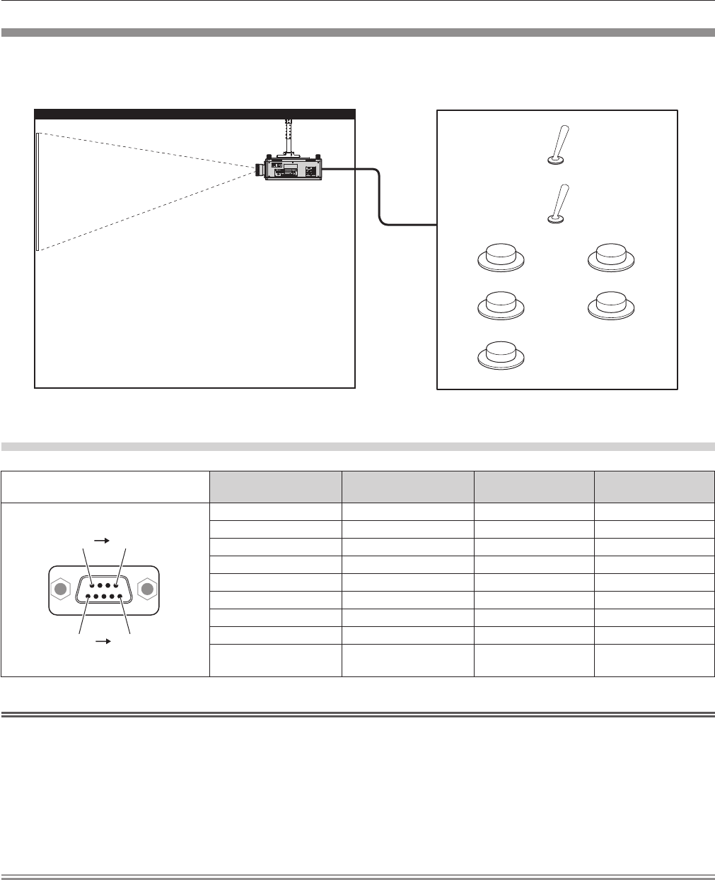
<REMOTE 2 IN> terminal
It is possible to control the projector remotely (by external contact) from a control panel located away from the
projector where remote control signals cannot reach.
Use the <REMOTE 2 IN> terminal on the connecting terminals of the projector to connect to the control panel.
Remote control Contact control
Remote control/contact control
Standby Lit
Light source
RGB1 DIGITAL LINK
RGB2 HDMI
DVI-D
Installation locations in meeting rooms, etc. Remote control board in another location
Pin assignments and signal names
D-Sub 9-pin
Outside view
Pin No. Signal name Open (H) Short (L)
(1) (5)
(6) (9)
(1) GND ― GND
(2) POWER OFF ON
(3) RGB1 Other RGB1
(4) RGB2 Other RGB2
(5) DIGITAL LINK Other DIGITAL LINK
(6) HDMI Other HDMI
(7) DVI-D Other DVI-D
(8) SHUTTER OFF ON
(9) ENABLE / DISABLE
Controlled by remote
control
Controlled by external
contact
Attention
f When controlling, make sure to short-circuit pins (1) and (9).
f When pins (1) and (9) are short-circuited, the following buttons on the control panel and the remote control are disabled. Commands for
RS-232C and network functions corresponding to these functions are also disabled.
g Power on <b> button, power standby <v> button, <SHUTTER> button
f When pins (1) and (9) are short-circuited, and then any pins from (3) to (7) and the pin (1) are short-circuited, the following buttons on the
control panel and the remote control are disabled. Commands for RS-232C and network functions corresponding to these functions are also
disabled.
g Power on <b> button, power standby <v> button, <RGB1> button, <RGB2> button, <DIGITAL LINK> button, <DVI-D> button, <HDMI>
button, <SDI 1/2> button or <SDI> button, <INPUT MENU> button, <SHUTTER> button
Note
f For pin (2) to pin (8) settings, you can make changes if you set [REMOTE2 MODE] to [USER]. (x page 140)