
Operation Manual
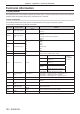
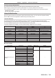
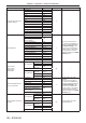
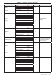
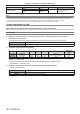
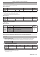
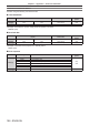
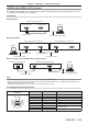
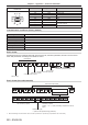
Table Of Contents
- Read this first!
- Chapter 1 Preparation
- Chapter 2 Getting Started
- Chapter 3 Basic Operations
- Switching on/off the projector
- Projecting
- Operating with the remote control
- Switching the input
- Using the shutter function
- Using the on-screen display function
- Using the automatic setup function
- Switching the image aspect ratio
- Using the function button
- Displaying internal test pattern
- Using the status function
- Using the AC voltage monitor function
- Setting ID number of the remote control
- Chapter 4 Settings
- Menu navigation
- [PICTURE] menu
- [POSITION] menu
- [ADVANCED MENU] menu
- [DISPLAY LANGUAGE] menu
- [3D SETTINGS] menu
- [DISPLAY OPTION] menu
- [COLOR MATCHING]
- [LARGE SCREEN CORRECTION]
- [SCREEN SETTING]
- [AUTO SIGNAL]
- [AUTO SETUP]
- [BACKUP INPUT SETTING]
- [SIMUL INPUT SETTING]
- [RGB IN]
- [DVI-D IN]
- [HDMI IN]
- [DIGITAL LINK IN]
- [SDI IN]
- [ON-SCREEN DISPLAY]
- [IMAGE ROTATION]
- [BACK COLOR]
- [STARTUP LOGO]
- [UNIFORMITY]
- [SHUTTER SETTING]
- [FREEZE]
- [WAVEFORM MONITOR]
- [CUT OFF]
- [PROJECTOR SETUP] menu
- [PROJECTOR ID]
- [PROJECTION METHOD]
- [OPERATION SETTING]
- [LIGHT OUTPUT]
- [BRIGHTNESS CONTROL]
- [STANDBY MODE]
- [NO SIGNAL SHUT-OFF]
- [NO SIGNAL LIGHTS-OUT]
- [INITIAL STARTUP]
- [STARTUP INPUT SELECT]
- [DATE AND TIME]
- [SCHEDULE]
- [RS-232C]
- [REMOTE2 MODE]
- [FUNCTION BUTTON]
- [LENS CALIBRATION]
- [LENS MEMORY]
- [STATUS]
- [AC VOLTAGE MONITOR]
- [SAVE ALL USER DATA]
- [LOAD ALL USER DATA]
- [INITIALIZE]
- [SERVICE PASSWORD]
- [P IN P] menu
- [TEST PATTERN] menu
- [SIGNAL LIST] menu
- [SECURITY] menu
- [NETWORK] menu
- Chapter 5 Maintenance
- Chapter 6 Appendix
Chapter 6 Appendix — Technical information
ENGLISH - 199
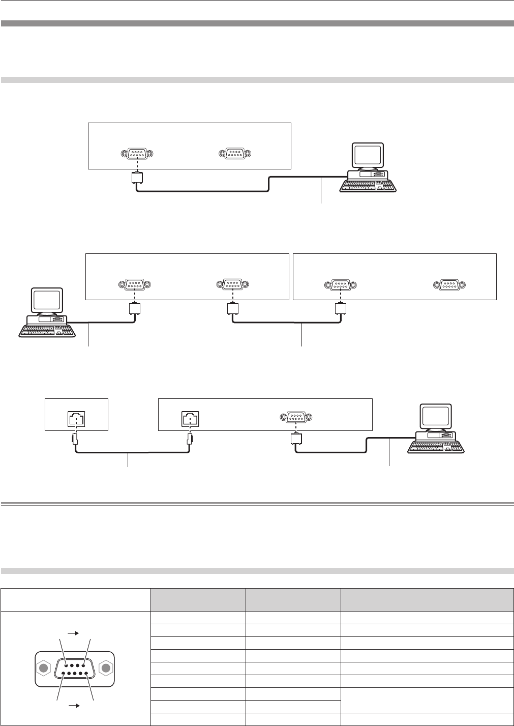
<SERIAL IN>/<SERIAL OUT> terminal
The <SERIAL IN>/<SERIAL OUT> terminal of the projector conforms with RS-232C so that the projector can be
connected to and controlled from a computer.
Connection
Single projector
Projector connecting terminals
Computer
D-Sub 9p (male)
Communication cable (straight)
D-Sub 9p (female) D-Sub 9p (male)
Multiple projectors
D-Sub 9p (female) D-Sub 9p (male)
Connecting terminals on projector 2
D-Sub 9p (female) D-Sub 9p (male)
Connecting terminals on projector 1
Computer
D-Sub 9p (male) D-Sub 9p (female)
D-Sub 9p (male)
Communication cableCommunication cable
When connecting using DIGITAL LINK compatible device
DIGITAL LINK compatible device
Computer
D-Sub 9p (female)
Projector connecting terminals
DIGITAL LINK DIGITAL LINK
D-Sub 9p (male)
Communication cable (straight)
LAN cable (straight)
Note
f The destination of [RS-232C] (x page 138) must be set according to the connection method.
f When connecting using a DIGITAL LINK compatible device, set the [PROJECTOR SETUP] menu → [STANDBY MODE] (x page 134) to
[NORMAL] to control the projector during standby.
When [STANDBY MODE] is set to [ECO], the projector cannot be control during standby.
Pin assignments and signal names
D-Sub 9-pin (female)
Outside view
Pin No. Signal name Details
(1) (5)
(6) (9)
(1) ― NC
(2) TXD Transmitted data
(3) RXD Received data
(4) ― NC
(5) GND Earth
(6) ― NC
(7) CTS
Connected internally
(8) RTS
(9) ― NC