Operating Instructions Functional Manual DLP™ Projector Commercial Use Model No. PT-RZ12K PT-RS11K The projection lens is sold separately. Thank you for purchasing this Panasonic product. ■■ This manual is common to all the models regardless of suffixes of the Model No. zzfor India PT-RZ12KD / PT-RS11KD zzfor other countries or regions PT-RZ12K / PT-RS11K ■■ Before operating this product, please read the instructions carefully and save this manual for future use.
Contents Contents 64 Read this first! 5 Projecting Selecting the input signal 64 How to adjust focus, zoom, and shift 64 Preparation Chapter 1 Adjusting the lens position and focus when the Fixed-focus Lens (Model No.
Contents [ADVANCED MENU] menu 95 125 [PROJECTOR SETUP] menu [DIGITAL CINEMA REALITY] [PROJECTOR ID] 95 125 [BLANKING] [PROJECTION METHOD] 95 125 [INPUT RESOLUTION] [OPERATION SETTING] 96 125 [CLAMP POSITION] [LIGHT OUTPUT] 96 129 [EDGE BLENDING] [BRIGHTNESS CONTROL] 97 130 [FRAME RESPONSE] [STANDBY MODE] 98 134 [FRAME CREATION] [NO SIGNAL SHUT-OFF] 99 134 [FRAME LOCK] [NO SIGNAL LIGHTS-OUT] 99 134 [RASTER POSITION] [INITIAL STARTUP] 100 135 [START
Contents [NETWORK] menu 156 [DIGITAL LINK MODE] 156 [DIGITAL LINK SETUP] 156 [DIGITAL LINK STATUS] 157 [NETWORK SETUP] 157 [NETWORK CONTROL] 158 [NETWORK STATUS] 158 [DIGITAL LINK MENU] 159 [Art-Net SETUP] 159 [Art-Net CHANNEL SETTING] 159 [Art-Net STATUS] 160 Network connection 160 Connecting to a twisted-pair-cable transmitter 161 Accessing from the web browser 162 Chapter 5 Maintenance Light source/temperature/filter indicators 182 When an indicator lights
Read this first! Read this first! WARNING: THIS APPARATUS MUST BE EARTHED. WARNING: To prevent damage which may result in fire or shock hazard, do not expose this appliance to rain or moisture. This device is not intended for use in the direct field of view at visual display workplaces. To avoid incommoding reflexions at visual display workplaces this device must not be placed in the direct field of view. The equipment is not intended for used at a video workstation in compliance BildscharbV.
Read this first! Notice on laser (for USA and Canada) This projector is the Class 3R laser product that complies with IEC 60825-1:2007. For North America “Complies with 21 CFR Parts 1040.10 and 140.11 except for deviations pursuant to Laser Notice No.50 dated june 24.
Read this first! CAUTION (North/Middle/South America/Taiwan) Power Supply: CAUTION: This Projector is designed to operate on 100 V - 240 V, 50 Hz/60 Hz AC, house current only. The AC power cord which is supplied with the projector as an accessory can only be used for power supplies up to 125 V. If you need to use higher voltages than this, you will need to obtain a separate 250 V power cord. If you use the accessory cord in such situations, fire may result.
Read this first! FCC NOTICE (USA) Verification Model Number: Trade Name: Responsible Party: Address: General Contact: Projector Contact: PT-RZ12K / PT-RS11K Panasonic Panasonic Corporation of North America Two Riverfront Plaza, Newark, NJ 07102-5490 http://www.panasonic.com/support http://panasonic.net/avc/projector/ This device complies with Part 15 of the FCC Rules.
Read this first! IMPORTANT: THE MOLDED PLUG (U.K. only) FOR YOUR SAFETY, PLEASE READ THE FOLLOWING TEXT CAREFULLY. This appliance is supplied with a molded three pin mains plug for your safety and convenience. A 13 amp fuse is fitted in this plug. Should the fuse need to be replaced, please ensure that the replacement fuse has a rating of 13 amps and that it is approved by ASTA or BSI to BS1362. Check for the ASTA mark or the BSI mark on the body of the fuse.
Read this first! WARNING: rr POWER The wall outlet or the circuit breaker shall be installed near the equipment and shall be easily accessible when problems occur. If the following problems occur, cut off the power supply immediately. Continued use of the projector in these conditions will result in fire or electric shock. ff If foreign objects or water get inside the projector, cut off the power supply. ff If the projector is dropped or the cabinet is broken, cut off the power supply.
Read this first! WARNING: Do not look at or place your skin into the light emitted from the lens while the projector is being used. Doing so can cause burns or loss of sight. ff Strong light is emitted from the projector’s lens. Do not look at or place your hands directly into this light. ff Be especially careful not to let young children look into the lens. In addition, turn off the power and switch off the main power when you are away from the projector.
Read this first! CAUTION: rr POWER When disconnecting the power cord, be sure to hold the power plug and power connector. If the power cord itself is pulled, the lead will become damaged, and fire, short-circuits or serious electric shocks will result. When not using the projector for an extended period of time, disconnect the power plug from the wall outlet. Failure to do so may result in fire or electric shock.
Read this first! CAUTION: rr ACCESSORIES When not using the projector for an extended period of time, remove the batteries from the remote control. Failure to observe this will cause the batteries to leak, overheat, catch fire or explode, which may result in fire or contamination of surrounding area. rr MAINTENANCE Do not attach the air filter unit while it is wet. Doing so may result in electric shock or malfunctions. ff After you clean the air filter units, dry them thoroughly before reattaching them.
Read this first! To remove the battery Remote Control Battery 1. Press the guide and lift the cover. 2. Remove the batteries. (ii) (i) Brazil Only Brasil Apenas rr Manuseio de baterias usadas BRASIL Após o uso, as pilhas e/ou baterias deverão ser entregues ao estabelecimento comercial ou rede de assistência técnica autorizada. Cobrir os terminais positivo (+) e negativo (-) com uma fita isolante adesiva, antes de depositar numa caixa destinada para o recolhimento.
rTrademarks r ffSOLID SHINE is a trademark of Panasonic Corporation. ffWindows and Internet Explorer are registered trademarks or trademarks of Microsoft Corporation in the United States and other countries. ffMac, Mac OS, and Safari are trademarks of Apple Inc., registered in the United States and other countries. ffPJLinkTM is a registered trademark or pending trademark in Japan, the United States, and other countries and regions.
Features of the Projector Quick Steps For details, refer to the corresponding pages. High luminance and high contrast ▶▶With the high efficient optical system that maximizes the output of the solid-state light source, and unique drive system, high luminance of 12 000 lm and high contrast of 20 000:1 are realized in addition to the high color reproduction. 1. Set up the projector. (x page 34) 2. Attach the projection lens (optional). (x page 46) Easy and highly flexible setup 3.
Chapter 1 Preparation This chapter describes things you need to know or check before using the projector.
Chapter 1 Preparation — Precautions for use Precautions for use Cautions when transporting ffBefore using the projector, remove the dust sponge from the mounting portion of the projection lens and store it for the future use. When transporting the projector, remove the projection lens before attaching the dust sponge. Otherwise dust will accumulate inside and may cause malfunctions. ffTransport the projector with 2 or more people.
Chapter 1 Preparation — Precautions for use rDo r not install the projector at an altitude of 4 200 m (13 780') or higher above sea level. rDo r not use the projector in a location that the ambient temperature exceeds 50 °C (122 °F). Using the projector in a location that the altitude is too high or the ambient temperature is too high may reduce the life of the components or result in malfunctions.
Chapter 1 Preparation — Precautions for use ffWhen installing the projector in a method other than the floor installation using the adjustable feet, or the ceiling installation, remove the adjustable feet (4 locations) and use the six screw holes for ceiling mount to fix the projector to a mount (as shown in the figure). (Screw diameter: M6, tapping depth inside the projector: 27 mm (1-1/16"), torque: 4 ± 0.
Chapter 1 Preparation — Precautions for use ffPrevent hot and cool air from the air conditioning system to blow directly to the ventilation ports (intake and exhaust) of the projector. 500 mm (19-11/16") or longer 500 mm (19-11/16") or longer 500 mm (19-11/16") or longer 100 mm (3-15/16") or longer ffDo not install the projector in a confined space. When installing the projector in a confined space, provide air conditioning or ventilation separately.
Chapter 1 Preparation — Precautions for use Art-Net “Art-Net” is an Ethernet communication protocol based on the TCP/IP protocol. By using the DMX controller and the application software, illumination and stage system can be controlled. Art-Net is made based on DMX512 communication protocol.
Chapter 1 Preparation — Precautions for use The luminance can be maintained as much as possible for the same runtime by setting the [PROJECTOR SETUP] menu → [OPERATION SETTING] → [CONSTANT MODE] to [AUTO]. These times are rough estimate when the projector is used without changing the [OPERATING MODE] and [CONSTANT MODE] settings, and will vary depending on individual difference and usage condition.
Chapter 1 Preparation — Precautions for use Accessories Make sure that the following accessories are provided with your projector. Numbers enclosed in < > show the number of accessories.
Chapter 1 Preparation — Precautions for use Contents of the supplied CD-ROM The contents of the supplied CD-ROM are as follows. Instruction/list (PDF) Software Operating Instructions – Functional Manual Multi Monitoring & Control Software Operating Instructions Logo Transfer Software Operating Instructions List of Compatible Device This is a list of display models (projector or flat panel display) that Models are compatible with the software contained in the CD-ROM and their restrictions.
Chapter 1 Preparation — About your projector About your projector Remote control Front Top 1 2 3 21 11 12 13 4 5 6 7 14 15 16 Bottom A strap can be attached depending on the usage. 8 9 17 10 18 22 19 20 1 Remote control indicator Blinks if any button in the remote control is pressed. 2 Power on button Sets the projector to projection mode when the switch on the projector is set to and the power is turned off (standby mode).
Chapter 1 Preparation — About your projector ff Avoid contact with liquids or moisture. ff Do not attempt to modify or disassemble the remote control. ff Do not swing the remote control holding onto the strap when a strap is attached. ff Observe the following instructions that are indicated on the caution label at the back of the remote control: gg Do not use old battery with new one. gg Do not use batteries other than the type specified. gg Be sure the batteries are inserted properly.
Chapter 1 Preparation — About your projector Projector body Side Front 1 2 3 4 5 6 7 8 7 Rear 8 12 13 9 8 14 10 Bottom 15 16 11 4 Light source indicator Indicates the status of light source 2. 5 Temperature indicator Indicates the internal temperature status. 6 Filter indicator Indicates the status of the air filter unit. 7 Adjustable feet Adjusts the projection angle.
Chapter 1 Preparation — About your projector rrControl panel 1 2 3 4 5 6 7 8 9 10 11 12 13 14 15 16 1 Power on button Sets the projector to projection mode when the switch on the projector is set to and the power is turned off (standby mode). 10 button Automatically adjusts the image display position while the image is projected. [PROGRESS] is displayed while in automatic adjustment.
Chapter 1 Preparation — About your projector rrConnecting terminals 1 2 6 3 5 7 1 terminal/ terminal These are terminals to connect the remote control for serial control in a multiple projector environment. 2 terminal This is a terminal to remotely control the projector using the external control circuit. 3 terminal This is the RS‑232C compatible terminal to externally control the projector by connecting a computer.
Chapter 1 Preparation — Preparing the remote control Preparing the remote control Inserting and removing the batteries (ii) (i) Fig. 1 1) Open the cover. (Fig. 1) 2) Insert the batteries and close the cover (insert the m side first). (Fig. 2) ffWhen removing the batteries, perform the steps in reverse order. Fig.
Chapter 1 Preparation — Preparing the remote control Connecting the remote control to the projector with a cable If you control the multiple projectors with a single remote control, use commercially available M3 stereo mini jack cables to connect to the / terminals of the projectors. The remote control is effective even in places where an obstacle stands in the light path or where devices are susceptible to outside light.
Chapter 2 Getting Started This chapter describes things you need to do before using the projector such as the setup and connections.
Chapter 2 Getting Started — Setting up Setting up Installation mode The installation modes of the projector are as follows. Set the [PROJECTOR SETUP] menu → [PROJECTION METHOD] (x page 125) depending on the installation mode.
Chapter 2 Getting Started — Setting up Parts for ceiling mount (optional) The projector can be installed on the ceiling by combining the optional Ceiling Mount Bracket (Model No.: ET‑PKD520H (for High Ceilings), ET‑PKD520S (for Low Ceilings)) and Ceiling Mount Bracket (Model No.: ET‑PKD520B (Projector Mount Bracket)). ffBe sure to use the Ceiling Mount Bracket specified for this projector. ffRefer to the Installation Instructions of the Ceiling Mount Bracket when installing and setting up the projector.
Chapter 2 Getting Started — Setting up rrFor the Fixed-focus Lens (Model No.
Chapter 2 Getting Started — Setting up [GEOMETRY] projection range [VERTICAL KEYSTONE] (viewed from the side) [HORIZONTAL KEYSTONE] (viewed from above) Screen Screen Vertical arc correction (viewed from the side) Horizontal arc correction (viewed from above) Projection distance Arc radius Projection distance Arc radius Screen Screen Arc center Arc center Screen Screen Projection distance Arc radius Projection distance Arc radius ENGLISH - 37
Chapter 2 Getting Started — Setting up Standard status Only [KEYSTONE] used [KEYSTONE] and [CURVED] used together Only [CURVED] used Projection lens Model No. Vertical keystone correction angle α (°) Horizontal keystone correction angle β (°) Vertical keystone correction angle α (°) Horizontal keystone correction angle β (°) ET‑D75LE6 ±28 ±15 ±10 ±10 1.6 3.9 0.9 2.3 ET‑D75LE8 ±40 ±15 ±20 ±15 0.2 0.4 0.2 0.3 ET‑D75LE10 ±40 ±15 ±20 ±15 1.1 2.6 0.6 1.
Chapter 2 Getting Started — Setting up Projection distance of each projection lens A ±5 % error in listed projection distances may occur. When [GEOMETRY] is used, distance is corrected to become smaller than the specified image size. For PT‑RZ12K rrWhen the image aspect ratio is 16:10 (Unit: m) Lens type Projection lens Model No. Throw ratio*1 Projected image size Height Diagonal (SD) Width (SW) (SH) 1.78 (70") 0.942 1.508 2.03 (80") 1.077 1.723 2.29 (90") 1.212 1.939 2.54 (100") 1.346 2.154 3.
Chapter 2 Getting Started — Setting up rrWhen the image aspect ratio is 16:9 (Unit: m) Lens type Projection lens Model No. Throw ratio*1 Projected image size Height Diagonal (SD) Width (SW) (SH) 1.78 (70") 0.872 1.550 2.03 (80") 0.996 1.771 2.29 (90") 1.121 1.992 2.54 (100") 1.245 2.214 3.05 (120") 1.494 2.657 3.81 (150") 1.868 3.321 5.08 (200") 2.491 4.428 6.35 (250") 3.113 5.535 7.62 (300") 3.736 6.641 8.89 (350") 4.358 7.748 10.16 (400") 4.981 8.855 12.70 (500") 6.226 11.069 15.24 (600") 7.472 13.
Chapter 2 Getting Started — Setting up rrWhen the image aspect ratio is 4:3 (Unit: m) Lens type Projection lens Model No. Throw ratio*1 Projected image size Height Diagonal (SD) Width (SW) (SH) 1.78 (70") 1.067 1.422 2.03 (80") 1.219 1.626 2.29 (90") 1.372 1.829 2.54 (100") 1.524 2.032 3.05 (120") 1.829 2.438 3.81 (150") 2.286 3.048 5.08 (200") 3.048 4.064 6.35 (250") 3.810 5.080 7.62 (300") 4.572 6.096 8.89 (350") 5.334 7.112 10.16 (400") 6.096 8.128 12.70 (500") 7.620 10.160 15.24 (600") 9.144 12.
Chapter 2 Getting Started — Setting up For PT‑RS11K rrWhen the image aspect ratio is 4:3 (Unit: m) Lens type Projection lens Model No. Throw ratio*1 Projected image size Height Diagonal (SD) Width (SW) (SH) 1.78 (70") 1.067 1.422 2.03 (80") 1.219 1.626 2.29 (90") 1.372 1.829 2.54 (100") 1.524 2.032 3.05 (120") 1.829 2.438 3.81 (150") 2.286 3.048 5.08 (200") 3.048 4.064 6.35 (250") 3.810 5.080 7.62 (300") 4.572 6.096 8.89 (350") 5.334 7.112 10.16 (400") 6.096 8.128 12.70 (500") 7.620 10.160 15.
Chapter 2 Getting Started — Setting up rrWhen the image aspect ratio is 16:9 (Unit: m) Lens type Projection lens Model No. Throw ratio*1 Projected image size Height Diagonal (SD) Width (SW) (SH) 1.78 (70") 0.872 1.550 2.03 (80") 0.996 1.771 2.29 (90") 1.121 1.992 2.54 (100") 1.245 2.214 3.05 (120") 1.494 2.657 3.81 (150") 1.868 3.321 5.08 (200") 2.491 4.428 6.35 (250") 3.113 5.535 7.62 (300") 3.736 6.641 8.89 (350") 4.358 7.748 10.16 (400") 4.981 8.855 12.70 (500") 6.226 11.069 15.24 (600") 7.472 13.
Chapter 2 Getting Started — Setting up Formula for calculating the projection distance per projection lens To use a projected image size not listed in this manual, check the projected image size SD (m) and use the respective formula to calculate projection distance. The unit of all the formulae is m. (Values obtained by the following calculation formulae contain a slight error.) When calculating a projection distance using image size designation (value in inches), multiply the value in inches by 0.
Chapter 2 Getting Started — Setting up For PT‑RS11K rrZoom Lens Projection lens Model No. ET‑D75LE6 ET‑D75LE10 ET‑D75LE20 ET‑D75LE30 ET‑D75LE40 ET‑D75LE8 Throw ratio Aspect ratio 1.0 - 1.2:1 Projection distance (L) formula Min. (LW) Max. (LT) 4:3 = 0.8150 x SD - 0.0566 = 0.9764 x SD - 0.0736 1.0 - 1.2:1 16:9 = 0.8976 x SD - 0.0566 = 1.0748 x SD - 0.0736 1.4 - 1.8:1 4:3 =1.1425 x SD - 0.0857 = 1.4767 x SD - 0.1085 1.4 - 1.8:1 16:9 = 1.2446 x SD - 0.0857 = 1.6086 x SD - 0.1085 1.8 - 2.
Chapter 2 Getting Started — Attaching/removing the projection lens (optional) Attaching/removing the projection lens (optional) Move the lens position to the home position before replacing or removing the projection lens. (x page 66) Attention ff Replace the projection lens after turning off the power of the projector. ff Do not touch the electric contacts of the projection lens. Dust or dirt may cause poor contact. ff Do not touch the surface of the projection lens with your bare hands.
Chapter 2 Getting Started — Attaching/removing the projection lens (optional) Removing the projection lens Remove the projection lens using the following procedure. Lens release button Fig. 1 1) Remove the lens fixing screw. ffUse a Phillips screwdriver to remove the first screw to the right of the mark on the projection lens (orange). 2) Remove the projection lens by turning it counterclockwise while pressing the lens release button. (Fig.
Chapter 2 Getting Started — Connecting Connecting Before connecting ffBefore connecting, carefully read the operating instructions for the external device to be connected. ffTurn off the power of all devices before connecting cables. ffTake note of the following points before connecting the cables. Failure to do so may result in malfunctions.
Chapter 2 Getting Started — Connecting terminal pin assignments and signal names Outside view (24) (17) (16) (9) (8) (1) Pin No. Signal name Pin No. Signal name (1) T.M.D.S data 2- (13) ― (2) T.M.D.S data 2+ (14) +5 V (3) T.M.D.S data 2/4 shield (15) GND (4) ― (16) Hot plug detection (5) ― (17) T.M.D.S data 0- (6) DDC clock (18) T.M.D.S data 0+ (7) DDC data (19) T.M.D.S data 0/5 shield (8) ― (20) ― (9) T.M.D.S data 1- (21) ― (10) T.M.D.
Chapter 2 Getting Started — Connecting For / terminals Digital VCR for commercial use SD-SDI signal, HD-SDI signal, or 3G-SDI signal Note ff Use the [PICTURE] menu → [SYSTEM SELECTOR] to switch the input format. ff Some external devices to be connected require the [DISPLAY OPTION] menu → [SDI IN] to be set. ff Use a 5CFB or higher (such as 5CFB, or 7CFB) or a Belden 1694A or higher connection cable to properly transmit images. Use a connection cable of 100 m (328'1") length or less.
Chapter 2 Getting Started — Connecting Connecting example using DIGITAL LINK Twisted-pair-cable transmitter based on the communication standard HDBaseTTM such as the optional DIGITAL LINK output supported device (Model No.: ET‑YFB100G, ET‑YFB200G) uses the twisted pair cable to transmit input images, Ethernet, and serial control signal, and the projector can input such digital signal to the terminal.
Chapter 2 Getting Started — Connecting ff For twisted-pair-cable transmitters of other manufacturers of which the operation has been verified with the projector, visit the Panasonic website (http://panasonic.net/avc/projector/). Note that the verification for devices of other manufacturers has been made for the items set by Panasonic Corporation, and not all the operations have been verified.
Chapter 3 Basic Operations This chapter describes basic operations to start with.
Chapter 3 Basic Operations — Switching on/off the projector Switching on/off the projector Connecting the power cord Make sure that the supplied power cord is securely fixed to the projector body to prevent it from being removed easily. Confirm that the switch is on the side before connecting the power cord. Use the power cord matching with the power supply voltage and the shape of the outlet. For details of power cord handling, refer to “Read this first!” (x page 5).
Chapter 3 Basic Operations — Switching on/off the projector Note ff While the power indicator lights in orange, the fan is running to cool the projector. ff For approximately 15 seconds after the projector is switched off, the indicator does not light up even if the power is switched on. Turn on the power again after the power indicator lights in red. ff The projector consumes power even in standby mode (power indicator lit in red).
Chapter 3 Basic Operations — Switching on/off the projector When the initial setting screen is displayed When the projector is switched on for the first time after purchase, as well as when [ALL USER DATA] is executed from the [PROJECTOR SETUP] menu → [INITIALIZE], the focus adjustment screen is displayed after projection starts, then the [INITIAL SETTING] screen is displayed. Set them according to the circumstances. In other occasions, you can change the settings by menu operations.
Chapter 3 Basic Operations — Switching on/off the projector Initial setting (operation setting) Set the items for the operating method depending on the projector’s application and duration of usage. After completed the initial setting, you can change the settings of each item from the [PROJECTOR SETUP] menu. If you change the settings while using the projector, the duration until the luminance of light source decreases by half may shorten or the luminance may decrease.
Chapter 3 6) Basic Operations — Switching on/off the projector Press qw to adjust. Adjustment Operation Brightness Runtime (estimate) Press w. The screen becomes brighter. The runtime becomes shorter. Press q. The screen becomes darker. The runtime becomes longer. 7) Press as to select [CONSTANT MODE]. 8) Press qw to switch the item. ffThe items will switch each time you press the button. [OFF] [AUTO] [PC] Range of adjustment 8.0 % - 100.
Chapter 3 Basic Operations — Switching on/off the projector Interrelation of luminance and runtime You can use the projector with desired brightness and duration of use by combining the settings of [MAX LIGHT OUTPUT LEVEL], [LIGHT OUTPUT], and [CONSTANT MODE] in [BRIGHTNESS CONTROL SETUP]. Interrelation of luminance and runtime is as follows. Make the initial setting (operation setting) depending on your desired duration of use and brightness of the projected image.
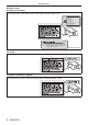
Chapter 3 Basic Operations — Switching on/off the projector Initial setting (installation setting) Set [PROJECTION METHOD] depending on the installation mode. Refer to “Installation mode” (x page 34) for details. After completed the initial setting, you can change the setting from the [PROJECTOR SETUP] menu → [PROJECTION METHOD]. 1) Press qw to switch the setting. 3/7 INITIAL SETTING PROJECTION METHOD FRONT/FLOOR Change the projection method if the screen display is upside down or inverted.
Chapter 3 Basic Operations — Switching on/off the projector Initial setting (screen setting) Set the screen format (aspect ratio) and display position of the image. After completed the initial setting, you can change the settings of each item from the [DISPLAY OPTION] menu → [SCREEN SETTING]. 1) Press as to select an item. 2) Press qw to switch the setting. 5/7 INITIAL SETTING 16:9 SCREEN FORMAT SCREEN POSITION Set as necessary for the screen in use.
Chapter 3 Basic Operations — Switching on/off the projector Initial setting (date and time) Set the local date and time. After completed the initial setting, you can change the setting from the [PROJECTOR SETUP] menu → [DATE AND TIME]. To set the date and time automatically, refer to “Setting the date and time automatically” (x page 136). 1) Press as to select an item.
Chapter 3 Basic Operations — Switching on/off the projector Note ff When the projector is switched on for the first time after purchase, as well as when [ALL USER DATA] is executed from the [PROJECTOR SETUP] menu → [INITIALIZE], the focus adjustment screen is displayed after projection starts, then the [INITIAL SETTING] screen is displayed. Refer to “When the initial setting screen is displayed” (x page 56) for details.
Chapter 3 Basic Operations — Projecting Projecting Check the projection lens attachment (x page 46), external device connection (x page 48), power cord connection (x page 54), switch on the power (x page 55) to start projecting. Select the video for projection, and adjust appearance of the projected image. Selecting the input signal Select an input signal.
Chapter 3 Basic Operations — Projecting ff When the main power is switched off during shift adjustment, a lens calibration error screen will be displayed during the next shift adjustment. Execute the [PROJECTOR SETUP] menu → [LENS CALIBRATION]. ff When the lens calibration error is displayed even though [LENS CALIBRATION] was executed, ask your dealer to repair the unit. Adjusting the lens position and focus when the Fixed-focus Lens (Model No.
Chapter 3 Basic Operations — Projecting Setting the lens position To move the lens position to the home position or the lens standard position, perform the following procedure. 1) Press the button on the remote control while the shift adjustment screen is displayed. ffThe [HOME POSITION] screen is displayed. LENS NORMAL HOME POSITION CHANGE ENTER 2) EXECUTE MENU CANCEL Press qw to switch the item. ffThe items will switch each time you press the button.
Chapter 3 Basic Operations — Projecting rrFor PT‑RS11K Projection lens Model No. ET‑D75LE8, ET‑D75LE10, ET‑D75LE20, ET‑D75LE30, ET‑D75LE40 ET‑D75LE6 Projected image height V 0.4 V 0.4 V 0.12 V 0.12 V 0.5 V 0.1 V Standard projection position Projected image height V Projected image width H 0.2 H 0.2 H 0.5 V 0.1 V Projected image width H 0.3 H 0.3 H Standard projection position Note ff When the optional Fixed-focus Lens (Model No.
Chapter 3 Basic Operations — Projecting rrFront view diagram of the lens mounter (viewed from the screen side) (a) Lens mount bracket (b) Fixing screws (c) Note ff Focus adjustment screws (a), (b), and (c) are adjusted with the lens attached.
Chapter 3 Basic Operations — Projecting 6) Press the button on the remote control or the button on the control panel to display the shift adjustment menu, and reset the screen position of the projected image on the screen surface back to an optimal state. 7) Perform focus adjustment again near the center of the screen and if it is still not enough, fine tune the amount of rotation of the adjustment screws. 8) When adjustments have been made, securely tighten the loosened fixing screws.
Chapter 3 Basic Operations — Operating with the remote control Operating with the remote control Switching the input The input for projection can be switched. Method to switch the input is as follows. ffPress the input selection button and directly specify the input to project. ffDisplay the input selection screen and select the input to project from the list. button Switching the input directly The input for projection can be switched by directly specifying it.
Chapter 3 Basic Operations — Operating with the remote control Note ff When the optional DIGITAL LINK output supported device (Model No.: ET‑YFB100G, ET‑YFB200G) is connected to the terminal, the input on the DIGITAL LINK output supported device changes each time the button is pressed. The input can also be changed using the RS‑232C control command.
Chapter 3 Basic Operations — Operating with the remote control Using the on-screen display function Turn off the on-screen display function (no display) when you do not wish the viewers to see the on-screen display, such as the menu or the input terminal name. button 1) Press the button. ffThe on-screen display disappears. 2) Press the button again. ffThe on-screen display appears.
Chapter 3 Basic Operations — Operating with the remote control Using the function button The button of the remote control can be used as a simplified shortcut button by assigning the following functions: [P IN P], [SUB MEMORY], [SYSTEM SELECTOR], [SYSTEM DAYLIGHT VIEW], [FREEZE], [WAVEFORM MONITOR], [LENS MEMORY LOAD], [LEFT/RIGHT SWAP], [PROJECTION METHOD] button 1) Press the button.
Chapter 3 Basic Operations — Operating with the remote control Using the AC voltage monitor function The value of input supply voltage can be displayed on the self-diagnosis display at the side of the projector. rrTo display during projection 1) Press the power on button. ffThe value of the input supply voltage is displayed only as numeric value on the self-diagnosis display. ffThe display will turn off automatically after approximately 3 seconds.
Chapter 4 Settings This chapter describes the settings and adjustments you can make using the on-screen menu.
Chapter 4 Settings — Menu navigation Menu navigation The on-screen menu (Menu) is used to perform various settings and adjustments of the projector. Navigating through the menu Operating procedure button 1) Press the
Chapter 4 4) Settings — Menu navigation Press as to select a sub-menu, and press qw or the button to change or adjust settings. ffSome items will switch in order as follows each time you press qw. A B C ffFor some items, press qw to display an individual adjustment screen with a bar scale as shown below. CONTRAST 0 ADJUST Note ff Pressing the
Chapter 4 Settings — Menu navigation Main menu item Page [DISPLAY LANGUAGE] 101 [3D SETTINGS] 102 [DISPLAY OPTION] 107 [PROJECTOR SETUP] 125 [P IN P] 146 [TEST PATTERN] 148 [SIGNAL LIST] 149 [SECURITY] 152 [NETWORK] 156 Sub-menu The sub-menu of the selected main menu item is displayed, and you can set and adjust items in the sub-menu.
Chapter 4 Sub-menu item [INPUT RESOLUTION] Settings — Menu navigation Factory default Page ― 96 [CLAMP POSITION] [24]*1 96 [EDGE BLENDING] [OFF] 97 [FRAME RESPONSE] [NORMAL] 98 [FRAME CREATION] [2] 99 [FRAME LOCK] ― 99 [RASTER POSITION] ― 100 *1 Depends on the signal input. Note ff Sub-menu items and factory default settings vary depending on the selected input terminal.
Chapter 4 Sub-menu item [WAVEFORM MONITOR] [CUT OFF] Settings — Menu navigation Factory default Page [OFF] 123 ― 124 Factory default Page [ALL] 125 [PROJECTOR SETUP] Sub-menu item [PROJECTOR ID] [PROJECTION METHOD] [OPERATION SETTING] [LIGHT OUTPUT] [BRIGHTNESS CONTROL] [FRONT/FLOOR] 125 ― 125 [100.
Chapter 4 Settings — Menu navigation [NETWORK] Sub-menu item Factory default Page [DIGITAL LINK MODE] [AUTO] 156 [DIGITAL LINK SETUP] ― 156 [DIGITAL LINK STATUS] ― 157 [NETWORK SETUP] ― 157 [NETWORK CONTROL] ― 158 [NETWORK STATUS] ― 158 [DIGITAL LINK MENU] [Art-Net SETUP] ― 159 [OFF] 159 [Art-Net CHANNEL SETTING] [2] 159 [Art-Net STATUS] ― 160 Note ff Some items may not be adjusted or used for certain signal formats to be input to the projector.
Chapter 4 Settings — [PICTURE] menu [PICTURE] menu On the menu screen, select [PICTURE] from the main menu, and select an item from the sub-menu. Refer to “Navigating through the menu” (x page 76) for the operation of the menu screen. [PICTURE MODE] You can switch to the desired picture mode suitable for the image source and the environment in which the projector is used. 1) Press as to select [PICTURE MODE]. 2) Press qw. ffThe [PICTURE MODE] individual adjustment screen is displayed.
Chapter 4 Settings — [PICTURE] menu Attention ff Adjust [BRIGHTNESS] first when you need to adjust the black level. [BRIGHTNESS] You can adjust the dark (black) part of the projected image. 1) Press as to select [BRIGHTNESS]. 2) Press qw or the button. ffThe [BRIGHTNESS] individual adjustment screen is displayed. 3) Press qw to adjust the level. Operation Adjustment Press w. Increases the brightness of the dark (black) parts of the screen. Press q.
Chapter 4 [USER1] [USER2] [3200K] - [9300K] Settings — [PICTURE] menu Adjusts white balance as desired. Refer to “Adjusting desired white balance” (x page 84) for details. Allows you to set in increments of 100 K. Select so that images become natural. Note ff When [PICTURE MODE] (x page 82) is set to [USER] or [DICOM SIM.], [DEFAULT] cannot be selected. ff When [COLOR MATCHING] (x page 107) adjustment is set to other than [OFF], [COLOR TEMPERATURE] is fixed to [USER1].
Chapter 4 Settings — [PICTURE] menu 6) Press the button. ffThe confirmation screen is displayed. 7) Press qw to select [OK], and press the button. ffThe [USER1] or [USER2] data is overwritten. ffIf you press qw to select [CANCEL] and then press the button, the data will not be overwritten. ffThe [WHITE BALANCE HIGH] screen is displayed. 8) Press as to select [RED], [GREEN], or [BLUE]. 9) Press qw to adjust the level. Note ff Adjust [COLOR TEMPERATURE] correctly.
Chapter 4 Settings — [PICTURE] menu Note ff DICOM is an abbreviation of “Digital Imaging and COmmunication in Medicine” and is a standard for medical imaging devices. Although the DICOM name is used, the projector is not a medical device, and should not be used for purposes such as diagnosis of display images. Changing the name of [USER1] or [USER2] 1) Press as to select [GAMMA]. 2) Press qw or the button. ffThe [GAMMA] individual adjustment screen is displayed.
Chapter 4 Settings — [PICTURE] menu [NOISE REDUCTION] You can reduce noises when the input image is degraded and noise is occurring in the image signal. 1) Press as to select [NOISE REDUCTION]. 2) Press qw or the button. ffThe [NOISE REDUCTION] individual adjustment screen is displayed. 3) Press qw to switch the item. ffThe items will switch each time you press the button. [OFF] No correction. [1] Slightly corrects the noise. [2] Moderately corrects the noise.
Chapter 4 Settings — [PICTURE] menu Setting item Details [DISABLE] [LIGHTS OUT TIMER] (Time setting until the light turns off) [0.0s] - [10.0s] [LIGHTS OUT SIGNAL LEVEL] (Setting of the brightness level of the signal to turn off the light) [0%] - [5%] [MANUAL INTENSITY] (Manual light source adjsutment) [0] - [255] [DYNAMIC GAMMA] (Adjustment of signal compensation) Does not turn off the light source.
Chapter 4 Settings — [PICTURE] menu Terminal System format For single link terminal, terminal For dual link 4) Select [AUTO], [480i YCBCR], [576i YCBCR], [720/50p YPBPR], [720/60p YPBPR], [1035/60i YPBPR], [1080/24p YPBPR], [1080/24sF YPBPR], [1080/25p YPBPR], [1080/30p YPBPR], [1080/50i YPBPR], [1080/60i YPBPR], [1080/50p YPBPR], [1080/60p YPBPR], [1080/24p RGB], [1080/24sF RGB], [1080/25p RGB], [1080/30p RGB], [1080/50i RGB], or [1080/60i RGB].
Chapter 4 Settings — [POSITION] menu [POSITION] menu On the menu screen, select [POSITION] from the main menu, and select an item from the sub-menu. Refer to “Navigating through the menu” (x page 76) for the operation of the menu screen. Note ff When the optional DIGITAL LINK output supported device (Model No.: ET‑YFB100G, ET‑YFB200G) is connected to the terminal, adjust the shift, aspect, and clock phase from the menu of DIGITAL LINK output supported device at first.
Chapter 4 [VID AUTO]*1 [AUTO]*2 [THROUGH] The projector identifies the video ID (VID) embedded in the video signals and displays the image by automatically switching the screen sizes between 4:3 and 16:9. This function is effective for NTSC signals. The projector identifies the video ID (VID) embedded in the video signals and displays the image by automatically switching the screen sizes between 4:3 and 16:9. This function is effective for 480i/480p signals.
Chapter 4 Settings — [POSITION] menu When [ASPECT] is set to [DEFAULT] 1) Press as to select [ZOOM]. 2) Press the button. ffThe [ZOOM] screen is displayed. 3) Press as to select [MODE]. 4) Press qw to switch the item. [INTERNAL] [FULL] Enlarges the size within the aspect range set with [SCREEN FORMAT]. Enlarges or reduces the size using the entire display area set with [SCREEN FORMAT]. 5) Press as to select [INTERLOCKED]. 6) Press qw to switch the item.
Chapter 4 Settings — [POSITION] menu [PC-1]*1 [PC-2]*1 Performs geometric adjustment using a computer. [PC-3]*1 *1 Advanced skills are necessary to use a computer to control geometric adjustment. Consult your dealer. Up to three geometric adjustments performed using the computer can be saved. Setting [KEYSTONE] or [CURVED] 1) Press as to select [GEOMETRY]. 2) Press qw to select [KEYSTONE] or [CURVED]. 3) Press the button. ffThe [GEOMETRY:KEYSTONE] or [GEOMETRY:CURVED] screen is displayed.
Chapter 4 Settings — [POSITION] menu [CURVED] [HORIZONTAL BALANCE] [VERTICAL BALANCE] [MAINTAIN ASPECT RATIO] Select [ON] to correct while keeping the aspect ratio. Setting [CORNER CORRECTION] 1) Press as to select [GEOMETRY]. 2) Press qw to select [CORNER CORRECTION]. 3) Press the button. ffThe [GEOMETRY:CORNER CORRECTION] screen is displayed. 4) Press as to select the item to adjust, and press the button. 5) Press asqw to adjust.
Chapter 4 Settings — [ADVANCED MENU] menu [ADVANCED MENU] menu On the menu screen, select [ADVANCED MENU] from the main menu, and select an item from the submenu. Refer to “Navigating through the menu” (x page 76) for the operation of the menu screen. [DIGITAL CINEMA REALITY] You can increase the vertical resolution and enhance the image quality by performing cinema processing when the PAL (or SECAM) 576i signal, the NTSC 480i signal, and 1080/50i, 1080/60i are input.
Chapter 4 Blanking correction Left side of the screen Right side of the screen Item Settings — [ADVANCED MENU] menu Operation Adjustment Press w. The blanking zone moves to the right. Press q. The blanking zone moves to the left. Press q. The blanking zone moves to the right. Press w. The blanking zone moves to the left.
Chapter 4 Settings — [ADVANCED MENU] menu [EDGE BLENDING] The edge blending function allows multiple projector images to be seamlessly overlapped by using the inclination of the brightness at the overlapped area. 1) Press as to select [EDGE BLENDING]. 2) Press qw to switch the item. ffThe items will switch each time you press the button. [OFF] Sets the edge blending function to off. [ON] Use the setting value preset in the projector for the inclination of the edge blending area.
Chapter 4 Settings — [ADVANCED MENU] menu 14) Press as to select an item, and press qw to adjust the setting. ffOnce the adjustment is completed, press the
Chapter 4 2) Settings — [ADVANCED MENU] menu Press qw to switch the item. ffThe items will switch each time you press the button. [NORMAL] Standard setting. [FAST]*1 Simplifies the image processing to reduce image frame delay. [FIXED]*2 Sets image frame delay to be constant regardless of the image position or magnification. *1 When input signals are other than interlaced signals, [FAST] cannot be set.
Chapter 4 Settings — [ADVANCED MENU] menu [RASTER POSITION] This will allow the position of the image to move within the display area arbitrarily when the input image is not using the whole display area. 1) Press as to select [RASTER POSITION]. 2) Press the button. ffThe [RASTER POSITION] screen is displayed. 3) Press asqw to adjust the position.
Chapter 4 Settings — [DISPLAY LANGUAGE] menu [DISPLAY LANGUAGE] menu On the menu screen, select [DISPLAY LANGUAGE] from the main menu, and display the sub-menu. Refer to “Navigating through the menu” (x page 76) for the operation of the menu screen. Changing the display language You can select the language of the on-screen display. 1) Press as to select the display language and press the button.
Chapter 4 Settings — [3D SETTINGS] menu [3D SETTINGS] menu On the menu screen, select [3D SETTINGS] from the main menu, and select an item from the sub-menu. Refer to “Navigating through the menu” (x page 76) for the operation of the menu screen. [3D SYSTEM SETTING] Set the image display method to be used during 3D signal input, according to the 3D system in use. 1) Press as to select [3D SYSTEM SETTING]. 2) Press qw to switch the item. ffThe items will switch each time you press the button.
Chapter 4 Settings — [3D SETTINGS] menu Select [6], [7], or [8] for the second and subsequent projectors. ffStereo synchronization is a signal having a 50 % duty cycle where High is for the left eye and Low is for the right eye. ff“H” is output to the 3D image display and “L” is output to the 2D image display from the terminal for which 3D trigger output is selected.
Chapter 4 [SHARED 2D/3D] [SEPARATE 2D/3D] Settings — [3D SETTINGS] menu Uses same correction data for 2D signal and 3D signal. Uses different correction data for 2D signal and 3D signal. Note ff Switch the setting of [COLOR MATCHING] (x page 107) while the signal to be adjusted is being input. [3D PICTURE BALANCE] Correct the difference when the images for left eye and right eye have different brightness or color. 1) Press as to select [3D PICTURE BALANCE]. 2) Press the button.
Chapter 4 Settings — [3D SETTINGS] menu Note ff This function is disabled when [3D SYSTEM SETTING] is set to anything other than [SINGLE]. ff The crosstalk may get larger or the displayed image may get darker when the setting does not match with the 3D system in use. [3D FRAME DELAY] Adjust the timing of the left-right switch of an image. 1) Press as to select [3D FRAME DELAY]. 2) Press qw to switch the item. [0us] - [25000us] Sets the amount in 10 us increments.
Chapter 4 Settings — [3D SETTINGS] menu [SAFETY PRECAUTIONS MESSAGE] Set to show or hide the safety precautions message related to 3D viewing when the projector is switched on. 1) Press as to select [SAFETY PRECAUTIONS MESSAGE]. 2) Press qw to switch the item. ffThe items will switch each time you press the button. [ON] Shows the safety precautions message related to 3D viewing when the projector is switched on.
Chapter 4 Settings — [DISPLAY OPTION] menu [DISPLAY OPTION] menu On the menu screen, select [DISPLAY OPTION] from the main menu, and select an item from the submenu. Refer to “Navigating through the menu” (x page 76) for the operation of the menu screen. [COLOR MATCHING] Correct the color difference between projectors when using multiple projectors simultaneously. Adjusting the color matching as desired 1) Press as to select [COLOR MATCHING]. 2) Press qw to switch the item.
Chapter 4 Settings — [DISPLAY OPTION] menu 4) Press as to select [MEASURED DATA]. 5) Press the button. ffThe [MEASURED DATA] screen is displayed. 6) Measure the current luminance (Y) and the chromaticity coordinates (x, y) using the colorimeter. 7) Press as to select a color, and press qw to adjust the setting. ffSet [AUTO TESTPATTERN] to [ON] to display a test pattern of selected colors. 8) Once all the input is completed, press the
Chapter 4 Model No. Settings — [DISPLAY OPTION] menu [SCREEN FORMAT] PT‑RS11K Range when [SCREEN POSITION] is selected [4:3] Cannot be adjusted. [16:9] Adjusts the vertical position between ‑132 and 131. 4) Press as to select [SCREEN POSITION]. ff[SCREEN POSITION] cannot be selected or adjusted when [SCREEN FORMAT] is set to the following item. PT‑RZ12K: [16:10] PT‑RS11K: [4:3] 5) Press qw to adjust [SCREEN POSITION].
Chapter 4 Settings — [DISPLAY OPTION] menu 2) Press the button. ffThe [AUTO SETUP] screen is displayed. 3) Press as to select [POSITION ADJUST]. 4) Press qw to switch the item. [ON] Adjust the screen position and size when automatic setup is executed. [OFF] Does not perform automatic adjustment. Adjusting signal level automatically 1) Press as to select [AUTO SETUP]. 2) Press the button. ffThe [AUTO SETUP] screen is displayed. 3) Press as to select [SIGNAL LEVEL ADJUST].
Chapter 4 Settings — [DISPLAY OPTION] menu Note ff Backup function is enabled when [BACKUP INPUT MODE] is set to [1], and the same signal is input to the and terminals. Alternatively, the backup function is enabled when [BACKUP INPUT MODE] is set to [2], and same signal is input to the terminal and the . ff To switch to the backup input signal using the backup function, make sure that the following three conditions are satisfied to be ready to use the function.
Chapter 4 [SIMUL INPUT SETTING] Settings — [DISPLAY OPTION] menu Usage of the input signal Details [1st FRAME INPUT] Uses the signal for the corresponding input as a signal for the odd frame. [2nd FRAME INPUT] Uses the signal for the corresponding input as a signal for the even frame. [AUTO(2D)]*1 *1 This can be set only when [SIMUL INPUT SETTING] is set to [HDMI/DVI-D] or [SDI1/SDI2]. [RGB IN] Set to match the signal to input to the terminal.
Chapter 4 Settings — [DISPLAY OPTION] menu 6) Press the button. ffThe [RESOLUTION] screen is displayed. 7) Press asqw to select [RESOLUTION]. ffSelect [1024x768p], [1280x720p], [1280x768p], [1280x800p], [1280x1024p], [1366x768p], [1400x1050p], [1440x900p], [1600x900p], [1600x1200p], [1680x1050p], [1920x1080p], [1920x1080i], or [1920x1200p]. 8) Press the button. ffThe [VERTICAL SCAN FREQUENCY] screen is displayed. 9) Press qw to select [VERTICAL SCAN FREQUENCY].
Chapter 4 Settings — [DISPLAY OPTION] menu Setting [EDID MODE] 1) Press as to select [DVI-D IN]. 2) Press the button. ffThe [DVI-D IN] screen is displayed. 3) Press as to select [EDID MODE]. 4) Press the button. ffThe [DVI-D EDID MODE] screen is displayed. 5) Press qw to switch [EDID MODE]. ffThe items will switch each time you press the button. [DEFAULT] [SCREEN FIT] [USER] Standard setting. Changes EDID data according to the [SCREEN FORMAT] setting.
Chapter 4 Settings — [DISPLAY OPTION] menu [64-940] Select this item when the signal output from the HDMI terminal of an external device (such as a Bluray disc player) is input to the terminal. [0-1023] Select this item when the signal output from the DVI‑D terminal of an external device (such as a computer) is input to the terminal via a conversion cable or similar cable.
Chapter 4 Settings — [DISPLAY OPTION] menu 2) Press the button. ffThe [DIGITAL LINK IN] screen is displayed. 3) Press as to select [SIGNAL LEVEL]. 4) Press qw to switch the item. ffThe items will switch each time you press the button. [AUTO] Automatically sets the signal level. [64-940] Select this item when the signal output from the HDMI terminal of an external device (Blu-ray disc player, etc.) is input to the terminal via a twisted-pair-cable transmitter.
Chapter 4 Settings — [DISPLAY OPTION] menu ff After configuring settings, your computer or video device or the projector may be required to be turned off and on. ff A signal may not be output with the resolution and vertical scanning frequency that have been set, depending on your computer or video device. [SDI IN] Set this function in accordance with the signal input to the / terminals. Setting [SDI LINK] 1) Press as to select [SDI IN]. 2) Press the button.
Chapter 4 Settings — [DISPLAY OPTION] menu 3) Press as to select [3G-SDI MAPPING]. 4) Press qw to switch the item. [AUTO] Automatically select [LEVEL A] or [LEVEL B]. [LEVEL A] Fixes to [LEVEL A]. [LEVEL B] Fixes to [LEVEL B]. Note ff This does not operate when the SD‑SDI signal or the HD‑SDI signal is input. [ON-SCREEN DISPLAY] Set the on-screen display. Setting [OSD POSITION] Set the position of the menu screen (OSD). 1) Press as to select [ON-SCREEN DISPLAY]. 2) Press the button.
Chapter 4 Settings — [DISPLAY OPTION] menu 3) Press as to select [OSD DESIGN]. 4) Press qw to switch the item. ffThe items will switch each time you press the button. [1] Sets to yellow. [2] Sets to blue. [3] Sets to white. [4] Sets to green. [5] Sets to peach. [6] Sets to brown. Setting [OSD MEMORY] Set hold for the position of the menu screen (OSD) cursor. 1) Press as to select [ON-SCREEN DISPLAY]. 2) Press the button. ffThe [ON-SCREEN DISPLAY] screen is displayed.
Chapter 4 [OFF] Settings — [DISPLAY OPTION] menu Hides the warning message. Note ff When [WARNING MESSAGE] is set to [OFF], the warning message will not be displayed on the projected image even if a warning status such as [TEMPERATURE WARNING] or [CLEAN THE AIR FILTER] is detected.
Chapter 4 Settings — [DISPLAY OPTION] menu [UNIFORMITY] Correct the brightness and color unevenness of the entire screen. Setting each color 1) Press as to select [UNIFORMITY]. 2) Press the button. ffThe [UNIFORMITY] screen is displayed. 3) Press as to select [WHITE], [RED], [GREEN], or [BLUE]. 4) Press qw to adjust the level. Item Operation Adjustment Press w. The lower-side color becomes pale, or the upper-side color becomes dark. Press q.
Chapter 4 4) Settings — [DISPLAY OPTION] menu Press qw to switch the item. [ENABLE] Turns off the light source and closes the mechanical shutter when the shutter function is enabled (shutter: closed). [DISABLE] Leaves the mechanical shutter open and turns off only the light source when the shutter function is enabled (shutter: closed). Note ff By closing the mechanical shutter, the malfunction of the DLP chip caused by high power laser ray entering the projection lens surface can be prevented.
Chapter 4 Settings — [DISPLAY OPTION] menu [OPEN] The projector goes into standby mode with the mechanical shutter opened when the projector is switched off. [CLOSE] The projector goes into standby mode with the mechanical shutter closed when the projector is switched off. [FREEZE] Pause the projected image temporarily regardless of the playback of the external device. 1) Press as to select [FREEZE]. 2) Press the button. ffPress the
Chapter 4 Settings — [DISPLAY OPTION] menu 1) Select “Select line (luminance)” on the waveform monitor. 2) Adjust black level. ffUse [BRIGHTNESS] in the on-screen menu [PICTURE] to adjust the black level 0 % of the video signal to the 0 % position of the waveform monitor. 3) Adjust white level. ffUse [CONTRAST] in the on-screen menu [PICTURE] to adjust the white level 100 % of the video signal to the 100 % position of the waveform monitor.
Chapter 4 Settings — [PROJECTOR SETUP] menu [PROJECTOR SETUP] menu On the menu screen, select [PROJECTOR SETUP] from the main menu, and select an item from the submenu. Refer to “Navigating through the menu” (x page 76) for the operation of the menu screen. [PROJECTOR ID] The projector has an ID number setting function that can be used when multiple projectors are used side by side to enable simultaneous control or individual control via a single remote control. 1) Press as to select [PROJECTOR ID].
Chapter 4 Settings — [PROJECTOR SETUP] menu [ECO]*1 Set this item to increase the life of the light source though it will lower the luminance than [NORMAL]. The estimated runtime is approximately 24 000 hours. [LONG LIFE1]*1 Set this item to increase the life of the light source though it will lower the luminance than [ECO]. The estimated runtime is approximately 43 000 hours. [LONG LIFE2]*1 Set this item to increase the life of the light source though it will lower the luminance than [LONG LIFE1].
Chapter 4 Settings — [PROJECTOR SETUP] menu 3) Press as to select [LIGHT OUTPUT]. 4) Press qw to adjust. Adjustment Operation Brightness Range of adjustment Runtime (estimate) Press w. The screen becomes brighter. The runtime becomes shorter. Press q. The screen becomes darker. The runtime becomes longer. 8.0 % - 100.0 % 5) Press as to select [APPLY]. 6) Press the button. 7) When the confirmation screen is displayed, press qw to select [OK], and press the button.
Chapter 4 Settings — [PROJECTOR SETUP] menu Setting [BRIGHTNESS CONTROL SETUP] Set the operation of the brightness control function. The [BRIGHTNESS CONTROL SETUP] setting is synchronized with the [PROJECTOR SETUP] menu → [BRIGHTNESS CONTROL] → [BRIGHTNESS CONTROL SETUP]. The most recent setting is reflected in both items. 1) Press as to select [OPERATION SETTING]. 2) Press the button. ffThe [OPERATION SETTING] screen is displayed. 3) Press as to select [CONSTANT MODE].
Chapter 4 Settings — [PROJECTOR SETUP] menu 14) Press the button. ffWhen [CONSTANT MODE] in [BRIGHTNESS CONTROL SETUP] is set to anything other than [OFF], the brightness and white balance of light source at the time when the button is pressed is recorded as the standard brightness and white balance. ffIf the button is pressed when [LINK] is set from [GROUP A] to [GROUP D], the group name is displayed on the screens of projectors that have been set in the same group.
Chapter 4 Settings — [PROJECTOR SETUP] menu [BRIGHTNESS CONTROL] The projector is equipped with a brightness sensor to measure brightness and color of the light source, and corrects brightness and white balance of the projected image according to the changes in brightness and color of the light source.
Chapter 4 Settings — [PROJECTOR SETUP] menu ffBrightness and color are measured at the specified time. The dynamic contrast function does not operate during measurement. 13) Press as to select [CALIBRATION MESSAGE]. 14) Press qw to switch the item. ffThe items will switch each time you press the button. [ON] Displays messages during calibration. [OFF] Does not display messages during calibration. 15) Press as to select [APPLY]. 16) Press the button.
Chapter 4 Settings — [PROJECTOR SETUP] menu [BRIGHTNESS CONTROL STATUS] screen display example When [CONSTANT MODE] of [BRIGHTNESS CONTROL SETUP] is set to [OFF] The screen shows the status that the brightness control is disabled. BRIGHTNESS CONTROL STATUS CONSTANT MODE OFF PROJECTOR MENU 1 RETURN When [CONSTANT MODE] of [BRIGHTNESS CONTROL SETUP] is set to [AUTO] and [LINK] is set to [OFF] The screen shows the status of the brightness control in one projector.
Chapter 4 Settings — [PROJECTOR SETUP] menu 5 Display the status by color. Green: There is an allowance for brightness correction. Yellow: There is little allowance for brightness correction. Red: There is a brightness control error. 6 Display error detailed messages. 7 Display error messages. When the message [Failed to apply BRIGHTNESS CONTROL to some projectors.] appears, it means that synchronization with the projector displayed in red has failed.
Chapter 4 Settings — [PROJECTOR SETUP] menu 12) Adjust [LIGHT OUTPUT] of each projector. ffAdjust [LIGHT OUTPUT] of all the other projectors so that the brightness will be the same as the projector with the least brightness. 13) Set [CONSTANT MODE] of [BRIGHTNESS CONTROL SETUP] to [AUTO], and [LINK] to [GROUP A] in all projectors. 14) Select [APPLY] of [BRIGHTNESS CONTROL SETUP] and press the button in all projectors. ffBrightness control starts.
Chapter 4 Settings — [PROJECTOR SETUP] menu Note ff The power indicator will blink slowly in green while the no signal lights-out function is operating and the light source is turned off. ff When [NO SIGNAL LIGHTS-OUT] is set to anything other than [DISABLE], the following are the conditions to turn the light source back on again from the condition that the light source has turned off by this function.
Chapter 4 3) Press as to select [TIME ZONE]. 4) Press qw to switch [TIME ZONE]. Settings — [PROJECTOR SETUP] menu Setting the date and time manually 1) Press as to select [DATE AND TIME]. 2) Press the button. ffThe [DATE AND TIME] screen is displayed. 3) Press as to select [ADJUST CLOCK]. 4) Press the button. ffThe [ADJUST CLOCK] screen is displayed. 5) Press as to select an item, and press qw to set the local date and time.
Chapter 4 Settings — [PROJECTOR SETUP] menu How to assign a program 1) Press as to select [SCHEDULE]. 2) Press qw to select [ON], and press the button. ffThe [SCHEDULE] screen is displayed. 3) Select and assign a program to each day of week. ffPress as to select the day of week, and press qw to select a program number. ffYou can set the program from No.1 to No.7. “‑ ‑ ‑” indicates that the program number has not been set. How to set a program Set up to 16 commands to each program.
Chapter 4 Settings — [PROJECTOR SETUP] menu Detailed settings of [COMMAND] [COMMAND] [NORMAL] [ECO] [OPERATING MODE]*2 Prioritizes luminance. Controls the power to increase the life of the light source with higher luminance. [LONG LIFE1] Controls the power to increase the life of the light source although the luminance is lower than that of [ECO]. [LONG LIFE2] Controls the power to increase the life of the light source although the luminance is even lower than that of [LONG LIFE1].
Chapter 4 Settings — [PROJECTOR SETUP] menu [9600] [19200] Select the proper speed. [38400] 7) Press as to select [(IN) PARITY]. 8) Press qw to switch the item. ffThe items will switch each time you press the button. [NONE] [EVEN] Select the parity condition. [ODD] Setting the communication condition of the terminal 1) Press as to select [RS-232C]. 2) Press the button. ffThe [RS-232C] screen is displayed. 3) Press as to select [(OUT) BAUDRATE].
Chapter 4 [OFF] Settings — [PROJECTOR SETUP] menu Does not return the response when an ID is designated as GROUP. Note ff When [INPUT SELECT] is set to [DIGITAL LINK], communication using that serial terminal is available only when the corresponding device (such as the optional DIGITAL LINK output supported device (Model No.: ET‑YFB100G, ET‑YFB200G)) is connected to the terminal. ff When transferring logos via the optional DIGITAL LINK output supported device (Model No.
Chapter 4 Settings — [PROJECTOR SETUP] menu 3) Press the button. ffThe confirmation screen is displayed. 4) Press qw to select [OK], and press the button. ffTo cancel, select [CANCEL]. ffThe lens moves up, down, left, and right to detect the lens shift limit value, and automatically set the home position and the ET‑D75LE90 lens standard position. ffThe lens stops to complete the calibration. Note ff [PROGRESS] is displayed in the menu during lens calibration.
Chapter 4 Settings — [PROJECTOR SETUP] menu ff The zoom and focus positions may have shifted after lens memory was loaded. Readjust as necessary. Beware of shift, as errors in zoom position are particularly significant. ff When a lens is replaced, readjust and save the lens memory again. ff If a lens without zoom function is used, the lens memory of the zoom position does not operate.
Chapter 4 3) Settings — [PROJECTOR SETUP] menu Press qw to switch the pages. ffThe page will change each time you press the button. [PROJECTOR TYPE] [PROJECTOR RUNTIME] [LIGHT RUNTIME] Displays the projector type and serial number of the projector. Displays the runtime of the projector. Displays the runtime of the light source 1 and the light source 2. [MAIN/SUB VERSION] Displays the main and sub versions of the firmware of the projector. [INTAKE AIR TEMP.
Chapter 4 2) Settings — [PROJECTOR SETUP] menu Press qw to switch the item. ffThe items will switch each time you press the button. [OFF] Disables the AC voltage monitor function. [ON] Enables the AC voltage monitor function. Note ff When [ON] is set, the value of the input supply voltage is always displayed in the self-diagnosis display while the main power of the projector is turned on.
Chapter 4 [NETWORK/E-MAIL] [LOGO IMAGE] Settings — [PROJECTOR SETUP] menu Returns [NETWORK SETUP] and [E-mail set up] to factory default settings. Deletes the image registered in [USER LOGO]. 5) Press the button. 6) When the confirmation screen is displayed, press qw to select [OK], and press the button. Note ff Even when [ALL USER DATA] is executed, the settings of [UNIFORMITY], [OPERATING MODE], [MAX LIGHT OUTPUT LEVEL], and [STANDBY MODE] are not initialized.
Chapter 4 Settings — [P IN P] menu [P IN P] menu On the menu screen, select [P IN P] from the main menu, and select an item from the sub-menu. Refer to “Navigating through the menu” (x page 76) for the operation of the menu screen. Using P IN P function Locate a separate, small sub screen in the main screen to project two images simultaneously. 1) Press as to select [P IN P MODE]. 2) Press the button. ffThe [P IN P MODE] screen is displayed. 3) Press as to select a function.
Chapter 4 Settings — [P IN P] menu 16) Press qw to switch the item. [MAIN WINDOW] The main window has display priority. [SUB WINDOW] The sub window has display priority. Note ff The P IN P function may not be available for some signals being input or terminals being selected. Refer to “Two-window display combination list” (x page 204) for details. ff Images in combination of DIGITAL LINK and other inputs cannot be displayed in P IN P.
Chapter 4 Settings — [TEST PATTERN] menu [TEST PATTERN] menu On the menu screen, select [TEST PATTERN] from the main menu. Refer to “Navigating through the menu” (x page 76) for the operation of the menu screen. [TEST PATTERN] Display the test pattern built-in to the projector. Settings of position, size, and other factors will not be reflected in test patterns. Make sure to display the input signal before performing various adjustments. 1) Press qw to switch the [TEST PATTERN] item.
Chapter 4 Settings — [SIGNAL LIST] menu [SIGNAL LIST] menu On the menu screen, select [SIGNAL LIST] from the main menu. Refer to “Navigating through the menu” (x page 76) for the operation of the menu screen. rrRegistered signal details Memory number: A1 (1-2) Sub memory number When the address number (A1, A2, ... L7, L8) signal is registered ffA name can be set for each sub memory (x page 151).
Chapter 4 3) Settings — [SIGNAL LIST] menu Press the button. ffThe selected signal will be deleted. Note ff A registered signal can also be deleted from [REGISTERED SIGNAL DELETE] on the [REGISTERED SIGNAL SETUP] screen. Protecting the registered signal 1) Press asqw to select the signal to protect. 2) Press the button. ffThe [REGISTERED SIGNAL STATUS] screen is displayed. 3) Press the button. ffThe [REGISTERED SIGNAL SETUP] screen is displayed.
Chapter 4 Settings — [SIGNAL LIST] menu ff When a signal to be input corresponds to multiple signals set in [WIDE], a registered signal with a high memory number receives priority. Example: a signal to be input that corresponds to memory numbers A2, A4 and B1 will be determined to be B1. ff When a registration signal is deleted, the settings are also deleted.
Chapter 4 Settings — [SECURITY] menu [SECURITY] menu On the menu screen, select [SECURITY] from the main menu, and select an item from the sub-menu. Refer to “Navigating through the menu” (x page 76) for the operation of the menu screen. ffWhen the projector is used for the first time Initial password: Press awsqawsq in order, and press the button. Attention ff When you select the [SECURITY] menu and press the button, entering a password is required.
Chapter 4 2) Settings — [SECURITY] menu Press qw to switch the item. ffThe items will switch each time you press the button. [OFF] Hides the security message. [TEXT] Displays the text set in the [SECURITY] menu → [TEXT CHANGE]. [USER LOGO] Displays the image registered by the user. Note ff To create/register the [USER LOGO] image, use “Logo Transfer Software” included in the supplied CD-ROM. [TEXT CHANGE] Edit the text to be displayed when [TEXT] is selected in [DISPLAY SETTING].
Chapter 4 Settings — [SECURITY] menu 4) Press the button. ffThe [CONTROL PANEL] screen or the [REMOTE CONTROL] screen is displayed. 5) Press as to select [CONTROL PANEL] or [REMOTE CONTROL]. 6) Press qw to switch [USER]. 7) Press as to select the button item to set. ffWhen [INPUT SELECT BUTTON] is selected, press the button, and then press as to select the button to set.
Chapter 4 4) Settings — [SECURITY] menu Press asqw to select [OK], and press the button. ffTo cancel, select [CANCEL]. Attention ff The initial password is “AAAA” by the factory default or when [ALL USER DATA] in [INITIALIZE] (x page 144) is executed. ff Change the password periodically that is hard to guess.
Chapter 4 Settings — [NETWORK] menu [NETWORK] menu On the menu screen, select [NETWORK] from the main menu, and select an item from the sub-menu. Refer to “Navigating through the menu” (x page 76) for the operation of the menu screen. [DIGITAL LINK MODE] Switch the communication method of the terminal of the projector. 1) Press as to select [DIGITAL LINK MODE]. 2) Press qw to switch the item. ffThe items will switch each time you press the button.
Chapter 4 Settings — [NETWORK] menu 5) Press as to select [STORE]. 6) Press the button. 7) When the confirmation screen is displayed, press qw to select [OK], and then press the button. Note ff The projector does not support 10BaseT Full/Half. When the projector is connected to a twisted-pair-cable transmitter 1) Press as to select [DIGITAL LINK SETUP]. 2) Press the button. ffThe [DIGITAL LINK SETUP] screen is displayed. 3) Press as to select [DUPLEX(DIGITAL LINK)].
Chapter 4 Settings — [NETWORK] menu [ON] If a DHCP server exists in the network where the projector is to be connected, obtains the IP address automatically. [OFF] If a DHCP server does not exist in the network where the projector is to be connected, set [IP ADDRESS], [SUBNET MASK], and [DEFAULT GATEWAY]. [DHCP] [IP ADDRESS] [SUBNET MASK] [DEFAULT GATEWAY] Enter the IP address when a DHCP server is not used. Enter the subnet mask when a DHCP server is not used.
Chapter 4 Settings — [NETWORK] menu [DIGITAL LINK MENU] When the optional DIGITAL LINK output supported device (Model No.: ET‑YFB100G, ET‑YFB200G) is connected to the terminal, the main menu of the connected DIGITAL LINK output supported device is displayed. Refer to the Operating Instructions of the DIGITAL LINK output supported device for details. Note ff [DIGITAL LINK MENU] cannot be selected when [EXTRON XTP] is set to [ON].
Chapter 4 Settings — [NETWORK] menu [LIGHT OUTPUT] Adjusts the amount of light. [INPUT SELECT] Switches the input. [LENS POSITION] Moves the lens position. [LENS H SHIFT] Adjusts the lens shift in the horizontal direction. [LENS V SHIFT] Adjusts the lens shift in the vertical direction. [LENS FOCUS] Adjusts the focus. [LENS ZOOM] Adjusts the zoom. [POWER] [SHUTTER] [GEOMETRY] [CUSTOM MASKING] Controls the power status. Controls the shutter. Performs geometric adjustment.
Chapter 4 Settings — [NETWORK] menu rrExample of a normal network connection Computer Projector LAN cable (straight) LAN cable (straight) Hub ff A web browser is required to use this function. Confirm that the web browser can be used beforehand. Supported browser: Internet Explorer 8.0/9.0/10.0/11.0 (Windows OS), Safari 6.0/7.0/8.0 (Mac OS) ff Communication with an E-mail server is required to use the E-mail function. Confirm that the E-mail can be used beforehand.
Chapter 4 Settings — [NETWORK] menu ff For the LAN cable between the twisted-pair-cable transmitter and the projector, use a cable that meets the following criteria: gg Conforming to CAT5e or higher standards gg Shielded type (including connectors) gg Straight-through gg Single wire ff The maximum transmission distance between the twisted-pair-cable transmitter and the projector is 100 m (328'1").
Chapter 4 4) Settings — [NETWORK] menu Click OK. ffThe [Projector status] page is displayed. Note ff If you use a web browser to control the projector, set [WEB CONTROL] to [ON] in [NETWORK CONTROL] (x page 158). ff Do not perform setting or control simultaneously by starting up multiple web browsers. Do not set or control the projector from multiple computers. ff Change the password first. (x page 177) ff The administrator rights allow use of all functions.
Chapter 4 Settings — [NETWORK] menu Descriptions of items 1 2 3 4 5 6 1 Page tab Switches pages by clicking this item. 4 [Detailed set up] The [Detailed set up] page is displayed by clicking this item. 2 [Status] The status of the projector is displayed by clicking this item. 5 [Change password] The [Change password] page is displayed by clicking this item. 3 [Projector control] The [Projector control] page is displayed by clicking this item.
Chapter 4 Settings — [NETWORK] menu [Projector status] page Click [Status] → [Projector status]. Display the status of the projector for the following items. 1 2 3 4 5 6 7 8 9 10 11 12 13 14 15 16 17 18 19 1 [PROJECTOR TYPE] Displays the type of the projector. 11 [LIGHT OUTPUT] Displays the setting status of [LIGHT OUTPUT]. 2 [MAIN VERSION] Displays the firmware version of the projector. 12 [INPUT] Displays the status of the selected input. 3 [POWER] Displays the status of the power.
Chapter 4 Settings — [NETWORK] menu Error information page When [Error (Detail)] or [Warning (Detail)] is displayed in the [SELF TEST] display field of the [Projector status] screen, click it to display the content of the error/warning. ffThe projector may go into the standby status to protect the projector depending on the contents of the error. 1 1 Self-diagnosis result display Displays the item check results. [OK]: Indicates that operation is normal. [FAILED]: Indicates that there is a problem.
Chapter 4 Item Settings — [NETWORK] menu Description [BRIGHTNESS SENSOR] There is a problem with the luminance sensor. If problems persist even after switching on the power, consult your dealer. [PHOSPHOR WHEEL1] There is a problem with the phosphor wheel 1 or phosphor wheel 1 drive circuit. Consult your dealer. [PHOSPHOR WHEEL2] There is a problem with the phosphor wheel 2 or phosphor wheel 2 drive circuit. Consult your dealer. [FILTER UNIT] The air filter unit is not attached.
Chapter 4 Settings — [NETWORK] menu [Access error log] page Click [Status] → [Access error log]. The error log on the web server is displayed such as access to the pages that do not exist or access with unauthorized user names or passwords. [Mail error log] page Click [Status] → [Mail error log]. E-mail error log is displayed if periodic E-mail sending has failed. Note ff [Access error log] and [Mail error log] display the recent few thousand accesses/requests.
Chapter 4 Settings — [NETWORK] menu [Basic control] page Click [Projector control] → [Basic control]. 1 2 3 4 5 6 1 [POWER] Turns on/off the power. 2 [SHUTTER] Switches whether to use the shutter function (enabled (shutter: closed)/disabled (shutter: open)). 3 [OSD] Switches on (display)/off (hide) the on-screen display function. 4 [SYSTEM] Switches the system method. 5 On-screen display of the projector Displays the same items as shown on the on-screen display of the projector.
Chapter 4 Settings — [NETWORK] menu [Network config] page Click [Detailed set up] → [Network config]. ffClick [Network config] to display the [CAUTION!] screen. ffThe current settings are displayed by pressing the [Next] button. ffClick [Change] to display the setting change screen. 1 2 3 4 5 6 7 8 1 [PROJECTOR NAME] Enter the name of the projector. Enter the host name if it is required when using a DHCP server etc. 2 [DHCP ON], [DHCP OFF] To enable the DHCP client function, set to [DHCP ON].
Chapter 4 Settings — [NETWORK] menu [Adjust clock] page Click [Detailed set up] → [Adjust clock]. 1 2 3 4 5 6 7 1 [Time Zone] Select the time zone. 5 [Date] Enter the date to be changed. 2 [Set time zone] Updates the time zone setting. 6 [Time] Enter the time to be changed. 3 [NTP SYNCHRONIZATION] Set to [ON] to adjust the date and time automatically. 7 [Submit] Updates the date and time settings.
Chapter 4 Settings — [NETWORK] menu [E-mail set up] page Send an E-mail to preset E-mail addresses (up to two addresses) when a problem has occurred. Click [Detailed set up] → [E-mail set up]. 1 2 3 4 5 6 1 [ENABLE] Select [Enable] to use the E-mail function. 2 [SMTP SERVER NAME] Enter the IP address or the server name of the E-mail server (SMTP). To enter the server name, the DNS server needs to be set up. 3 [MAIL FROM] Enter the E-mail address of the projector.
Chapter 4 Settings — [NETWORK] menu 7 8 7 8 9 7 [E-MAIL ADDRESS 1], [E-MAIL ADDRESS 2] Enter the E-mail address to be sent. Leave [E-MAIL ADDRESS 2] blank when two E-mail addresses are not to be used. 8 Settings of the conditions to send E-mail Select the conditions to send E-mail. [MAIL CONTENTS]: Select either [NORMAL] or [SIMPLE]. [ERROR]: Send an E-mail when an error occurred in the self-diagnosis.
Chapter 4 Settings — [NETWORK] menu [Authentication set up] page Set the authentication items when POP authentication or SMTP authentication is necessary to send an E-mail. Click [Detailed set up] → [Authentication set up]. 1 2 3 4 5 6 7 8 1 [Auth] Select the authentication method specified by your Internet service provider. 2 [SMTP Auth] Set when the SMTP authentication is selected. 3 [POP server name] Enter the POP server name.
Chapter 4 Settings — [NETWORK] menu Contents of E-mail sent Example of the E-mail sent when E-mail is set The following E-mail is sent when the E-mail settings have been established.
Chapter 4 Settings — [NETWORK] menu Example of the E-mail sent for an error The following E-mail is sent when an error has occurred. === Panasonic projector report(ERROR) === Projector Type : RZ12K Serial No : 123456789012 ----- check system ----MAIN CPU BUS [ FAILED ] FAN [ OK ] INTAKE AIR TEMPERATURE [ OK ] OPTICS MODULE TEMPERATURE [ OK ] EXHAUST AIR TEMPERATURE [ OK ] LD1 TEMPERATURE [ OK ] LD2 TEMPERATURE [ OK ] LD1 STATUS [ OK ] LD2 STATUS [ OK ] SHUTTER(MUTE-SHUTTER) [ OK ] INTAKE AIR TEMP.
Chapter 4 Settings — [NETWORK] menu [Change password] page Click [Change password]. 1 2 3 1 [Administrator] Used to change the setting of the [Administrator]. 2 [User] Used to change the setting of the [User]. 3 [Next] Used to change the setting of the password. [Administrator] account 1 2 3 4 1 [Account] Displays the account to change. 2 [Current] [User name]: Enter the user name before the change. [Password]: Enter the current password.
Chapter 4 Settings — [NETWORK] menu [User] account 1 2 3 1 [Account] Displays the account to change. 2 [New] [User name]: Enter the desired new user name. (Up to 16 characters in single byte) [Password]: Enter the desired new password. (Up to 16 characters in single byte) [Password(Retype)]: Enter the desired new password again. 3 [OK] Determines the change of password. [Change password] (For user rights) Only the change of password is enabled under the user rights.
Chapter 4 Settings — [NETWORK] menu Operation page 1 2 3 4 5 6 7 1 [Tools], [Info], [Help] Tabs for selecting the setting, information, or help page of the projector. 4 [Input Select] Controls input selection. Not available when the power of the projector is turned off. 2 [POWER] Turns on/off the power. 5 Menu screen control buttons Navigates the menu screen. 3 [SHUTTER] Switches whether to use the shutter function (enabled (shutter: closed)/disabled (shutter: open)).
Chapter 4 Settings — [NETWORK] menu [Info] page Click [Info] in the operation page. 4 5 1 2 3 6 7 1 [Projector Name] Displays the projector name. 5 [Source] Displays the selected input. 2 [Mac Address] Displays the MAC address. 6 [Error Status] Displays the error status. 3 [Lamp1 Hours], [Lamp2 Hours] Displays the runtime of the light source 1 and the light source 2. 7 [Exit] Returns to the operation page. 4 [Power Status] Displays the status of the power.
Chapter 5 Maintenance This chapter describes methods of inspection when there are problems, maintenance, and replacement of the units.
Chapter 5 Maintenance — Light source/temperature/filter indicators Light source/temperature/filter indicators When an indicator lights up If a problem occurs inside the projector, the light source indicators /, temperature indicator , or filter indicator will inform you by lighting or blinking in red. Check the status of the indicators and take following measures.
Chapter 5 Maintenance — Light source/temperature/filter indicators Temperature indicator Indicator status Blinking in red (2 times) Lighting in red Internal temperature is high (warning). Internal temperature is high (standby status).
Chapter 5 Maintenance — Maintenance/replacement Maintenance/replacement Before performing maintenance/replacement ffMake sure to turn off the power before maintaining or replacing the unit. (x pages 54, 63) ffWhen switching off the projector, make sure to follow the procedures in “Switching off the projector” (x page 63). Maintenance Outer case Wipe off dirt and dust with a soft, dry cloth. ffIf the dirt is persistent, soak the cloth with water and wring it thoroughly before wiping.
Chapter 5 Maintenance — Maintenance/replacement ffAfter pulling out the air filter unit, remove large foreign objects and dust from the air filter unit compartment and the air intake port of the projector body if there are any. (Fig. 3) Cleaning the air filter unit Remove the air filter unit beforehand with the previously described procedure of “Removing the air filter unit”. Fig. 1 1) Fig. 2 Wash the air filter unit. (Fig.
Chapter 5 Maintenance — Maintenance/replacement Note ff Make sure that the air filter unit is properly attached before using the projector. If it is not properly attached, the projector will suck in dirt and dust causing a malfunction. ff If you use the projector without attaching the air filter unit, the filter indicator blinks in red and the message appears on the projected image for approximately 30 seconds.
Chapter 5 Maintenance — Troubleshooting Troubleshooting Review the following points. For details, see the corresponding pages. Problems Power does not turn on. No image appears. Image is fuzzy. Color is pale or grayish. Remote control does not respond. Menu screen does not appear. Buttons on the control panel do not operate. Image does not display correctly.
Chapter 5 Problems Cannot control the projector with Art-Net. The DIGITAL LINK input image is not displayed.
Chapter 5 Maintenance — Self-diagnosis display Self-diagnosis display There is a self-diagnosis display on the side of the projector. Self-diagnosis display will automatically display the value of the input supply voltage, or details of errors or warnings when they occur. (x page 29) The following list shows the alphanumeric symbol that is displayed when an error or a warning has occurred and its details. The input supply voltage is displayed only with the numeric value.
Chapter 5 Maintenance — Self-diagnosis display Error/warning display Details F50 Radiator fan 1 warning F51 Radiator fan 2 warning F52 Radiator fan 3 warning F53 Radiator fan 4 warning F54 Radiator fan 5 warning F55 Radiator fan 6 warning F56 Exhaust fan 1 warning F57 Exhaust fan 2 warning F58 Intake fan 1 warning F59 Intake fan 2 warning F61 LD 1 driver communication error F62 LD 2 driver communication error F70 Color prism fan 1 warning F71 Color prism fan 2 warning F72 Co
Chapter 6 Appendix This chapter describes specifications and after-sales service for the projector.
Chapter 6 Appendix — Technical information Technical information PJLink protocol The network function of this projector supports the PJLink class 1, and the PJLink protocol can be used to perform projector setting and projector status query operations from a computer. Control commands The following table lists the PJLink protocol commands that can be used to control the projector. ffx characters in tables are non-specific characters.
Chapter 6 Appendix — Technical information PJLink security authentication The password used for PJLink is the same as that of the password set for web control. When using the projector without security authentication, do not set a password for web control. ffFor specifications related to PJLink, visit the website of Japan Business Machine and Information System Industries Association. URL http://pjlink.jbmia.or.
Chapter 6 Control details INPUT SELECT (when [2] or [USER] is selected) Appendix — Technical information Performance Parameter No operation 0‑7 RGB1 8‑15 RGB2 16‑23 DVI‑D 24‑31 HDMI 32‑39 DIGITAL LINK 40‑47 SDI1 48‑55 SDI2 56‑63 No operation 64‑119 P IN P OFF 120‑127 P IN P execution, USER1 128‑135 P IN P execution, USER2 136‑143 P IN P execution, USER3 144‑151 No operation 152‑255 No operation 0‑31 Default value Remark 0 ― 0 “Move to the home position” is an operatio
Chapter 6 Control details POWER SHUTTER FADE-IN FADE-OUT (when [1] is selected) GEOMETRY CUSTOM MASKING FREEZE COLOR TINT RASTER PATTERN Appendix — Technical information Performance Parameter Standby 0‑63 No operation 64‑191 Power on 192‑255 SHUTTER: Open 0‑63 No operation 64‑191 SHUTTER: Close 192‑255 0.0s 0‑15 0.5s 16‑31 1.0s 32‑47 1.5s 48‑63 2.0s 64‑79 2.5s 80‑95 3.0s 96‑111 3.5s 112‑127 4.0s 128‑143 5.0s 144‑159 7.0s 160‑175 10.
Chapter 6 Control details Appendix — Technical information Performance ENABLE/DISABLE Parameter Disable 0‑127 Enable 128‑255 Default value Remark 0 When “Disable” is set, operations of all channels become unacceptable. Note ff If the projector is operated with the remote control or on the control panel, or by the control command while controlling the projector using the Art-Net function, the setting of the DMX controller or computer application may be different from the projector status.
Chapter 6 Appendix — Technical information Command transmission method Transmit using the following command formats.
Chapter 6 Appendix — Technical information Command transmission method Transmit using the following command formats.
Chapter 6 Appendix — Technical information / terminal The / terminal of the projector conforms with RS‑232C so that the projector can be connected to and controlled from a computer.
Chapter 6 D‑Sub 9-pin (male) Outside view (9) Pin No. Signal name (1) ― (6) (5) Appendix — Technical information (1) Details NC (2) RXD Received data (3) TXD Transmitted data (4) ― (5) GND (6) ― (7) RTS (8) CTS (9) ― NC Earth NC Connected internally NC Communication conditions (Factory default) Signal level RS‑232C-compliant Sync.
Chapter 6 Appendix — Technical information Attention ff If a command is sent after the light source starts lighting, there may be a delay in response or the command may not be executed. Try sending or receiving any command after 60 seconds. ff When transmitting multiple commands, be sure to wait until 0.5 seconds has elapsed after receiving the response from the projector before sending the next command. When transmitting a command which does not need a parameter, a colon (:) is not necessary.
Chapter 6 Appendix — Technical information Control command The following table lists the commands that can be used to control the projector using a computer. rrProjector control command Command PON Power on POF Power standby QPW Power query IIS Parameter/response string Details Switching the input signal ― Remark (parameter) To check if the power is on, use the “Power query” command.
Chapter 6 Appendix — Technical information terminal It is possible to control the projector remotely (by external contact) from a control panel located away from the projector where remote control signals cannot reach. Use the terminal on the connecting terminals of the projector to connect to the control panel.
Chapter 6 Appendix — Technical information Two-window display combination list l: P IN P (picture in picture) combination is possible a: P IN P (picture in picture) combination is possible through the same frequency ―: P IN P (picture in picture) combination is not possible Sub window RGB1 Main window Still image signal RGB1 input RGB2 input DVI‑D input HDMI input Movie signal*1 RGB2 Still image Movie*1 Y/C Video Still image Movie*1 ― ― ― ― l l ― ― ― ― l a Y/C signal ― ― ― ― l
Chapter 6 Appendix — Technical information Control device password To initialize your password, consult your distributor. Upgrade Kit If the optional Upgrade Kit (Model No.: ET‑UK20) is applied, the following functions are extended.
Chapter 6 Appendix — Technical information List of compatible signals The following table specifies the video signals compatible with the projector. ffSymbols that indicate formats are as follows. ggV: VIDEO, Y/C ggR: RGB ggY: YCBCR/YPBPR ggD: DVI‑D ggH: HDMI ggS: SDI Resolution (Dots) Compatible signal Scanning freq. Horizontal Vertical (kHz) (Hz) Plug and play*1 Dot clock freq. (MHz) Format ― V RGB2 DVI‑D EDID1 EDID2 EDID3 HDMI NTSC/NTSC4.43/ PAL‑M/PAL60 720 x 480i 15.7 59.
Chapter 6 Compatible signal 1024 x 768 Resolution (Dots) 1280 x 720 1280 x 768 1280 x 800 1280 x 960 1280 x 1024 1366 x 768 1400 x 1050 1440 x 900 1600 x 900 1600 x 1200 1680 x 1050 1920 x 1080 Horizontal Vertical (kHz) (Hz) Dot clock freq. (MHz) Plug and play*1 Format RGB2 DVI‑D EDID1 EDID2 EDID3 HDMI 1 024 x 768 39.6 50.0 51.9 R/D/H ― ― ― ― ― 48.4 60.0 65.0 R/D/H l ― l l l 1 024 x 768 56.5 70.1 75.0 R/D/H l ― l l l 1 024 x 768 60.0 75.0 78.
Chapter 6 Resolution (Dots) Compatible signal 1920 x 1200 Appendix — Technical information Scanning freq. Horizontal Vertical (kHz) (Hz) Plug and play*1 Dot clock freq. (MHz) Format RGB2 DVI‑D EDID1 EDID2 EDID3 HDMI 1 920 x 1 200 61.8 49.9 158.3 R/D/H ― ― ― ― ― 1 920 x 1 200*8 74.0 60.0 154.0 R/D/H l ― l l*10 l*10 1 920 x 1 200*9 74.6 59.9 193.
Chapter 6 Appendix — Technical information List of 3D compatible signals The following table specifies the 3D compatible video signals that the projector can project. ffAbbreviations for input formats and 3D formats in the table have the following meanings.
Chapter 6 3D compatible signal 1600 x 1200 1680 x 1050 1920 x 1080 1920 x 1200 Appendix — Technical information Scanning freq. HDMI DVI‑D Horizontal (kHz) Vertical (Hz) Dot clock freq. (MHz) FP SBS*1 TB FS SBS*1 TB LBL FS 1 600 x 1 200 75.0 60.0 162.0 ― ― ― ― l ― ― ― 1 600 x 1 200 61.8 49.9 131.5 ― ― ― ― l ― ― ― 1 680 x 1 050 65.3 60.0 146.3 ― ― ― ― l ― ― ― 1 680 x 1 050 54.1 50.0 119.5 ― ― ― ― l ― ― ― Resolution (Dots) 1 920 x 1 080 55.
Chapter 6 3D compatible signal 1600 x 1200 1680 x 1050 1920 x 1080 1920 x 1200 Resolution (Dots) Appendix — Technical information Scanning freq. Horizontal Vertical (kHz) (Hz) Dot clock freq. (MHz) RGB1/RGB2 SDI1/SDI2 SBS*1 TB LBL FS SBS*1 TB LBL 3G H‑D R1‑2 S1‑2 1 600 x 1 200 75.0 60.0 162.0 l ― ― ― ― ― ― ― ― ― ― 1 600 x 1 200 61.8 49.9 131.5 l ― ― ― ― ― ― ― ― ― ― 1 680 x 1 050 65.3 60.0 146.3 l ― ― ― ― ― ― ― ― ― ― 1 680 x 1 050 54.1 50.0 119.
Chapter 6 Appendix — Specifications Specifications The specifications of the projector are as follows. Power supply 100 V - 240 V ~ (100 V - 240 V alternating current), 50 Hz/60 Hz 1 200 W (12.0 A - 6.0 A) Power consumption When [STANDBY MODE] is set to [ECO]: 0.3 W When [STANDBY MODE] is set to [NORMAL]: 4 W Size DLP chip Display system Number of pixels PT‑RZ12K 24.4 mm (0.96") (aspect ratio 16:10) PT‑RS11K 24.1 mm (0.
Chapter 6 Appendix — Specifications rrApplicable scanning frequency Refer to “List of compatible signals” (x page 206) for the types of video signals that can be used with the projector. For video signal, Y/C signal Horizontal: 15.75 kHz, Vertical: 60 Hz; Horizontal: 15.
Chapter 6 Appendix — Specifications rrTerminal 1 set (BNC x 5 (RGB/YPBPR/YCBCR/YC/VIDEO x 1)) RGB signal terminal 0.7 V [p-p] 75 Ω (SYNC ON GREEN: 1.0 V [p-p] 75 Ω) SYNC/HD TTL high impedance, automatic positive/negative polarity compatible VD TTL high impedance, automatic positive/negative polarity compatible YPBPR signal Y: 1.0 V [p-p] including synchronization signal, PBPR: 0.7 V [p-p] 75 Ω Y/C signal Y: 1.0 V [p-p], C: 0.286 V [p-p] 75 Ω VIDEO signal 1.
Chapter 6 Appendix — Dimensions Dimensions 242 (9-17/32") 484 (19-1/16") 142 (5-19/32") 53.5 (2-3/32") 289 (11-3/8") 270 (10-5/8") 15 (19/32") 725 (28-17/32") Unit: mm 637 (25-3/32") 578 (22-3/4") * Actual dimensions may differ depending on the product.
Chapter 6 Appendix — Precautions for attaching the Ceiling Mount Bracket Precautions for attaching the Ceiling Mount Bracket ffWhen installing the projector to a ceiling, be sure to use the specified optional Ceiling Mount Bracket (Model No.: ET‑PKD520H (for High Ceilings), ET‑PKD520S (for Low Ceilings), ET‑PKD520B (Projector Mount Bracket)). The Ceiling Mount Bracket (Model No.: ET‑PKD520H (for High Ceilings), ET‑PKD520S (for Low Ceilings)) is used in combination with the Ceiling Mount Bracket (Model No.
Index Index 0–9 E P [3D COLOR MATCHING] 103 Early Warning Software 22 [PICTURE] 78, 82 105 97 82 [3D FRAME DELAY] [EDGE BLENDING] [PICTURE MODE] 103 80, 146 [3D INPUT FORMAT] button [P IN P] 104 29 146 [3D PICTURE BALANCE] P IN P function Projector body 106 26 78, 90 [3D SAFETY PRECAUTIONS] Remote control [POSITION] 79, 102 150 54 [3D SETTINGS] Expanding signal lock-in range Power cord 102 54 [3D SYNC SETTING] Power indicator F 102 [3D SYS
Index Switching off the projector 63 55 Switching on the projector 70 Switch the input signal 86 [SYSTEM DAYLIGHT VIEW] 88 [SYSTEM SELECTOR] T Temperature indicator 182 80, 148 [TEST PATTERN] button 26, 73 Remote control 153 [TEXT CHANGE] 83 [TINT] 187 Troubleshooting 204 Two-window U [UNIFORMITY] 121 205 Upgrade Kit V
Information for Users on Collection and Disposal of Old Equipment and used Batteries These symbols on the products, packaging, and/or accompanying documents mean that used electrical and electronic products and batteries should not be mixed with general household waste. For proper treatment, recovery and recycling of old products and used batteries, please take them to applicable collection points, in accordance with your national legislation and the Directives 2002/96/EC and 2006/66/EC.