e00_l8hbe_xe_7.
e00_l8hbe_xe_7.book Page 1 Tuesday, April 27, 2004 10:35 AM PRECAUTION WARNING: TO REDUCE THE RISK OF FIRE OR ELECTRIC SHOCK, DO NOT EXPOSE THIS APPLIANCE TO RAIN OR OTHER MOISTURE. To avoid electrical shock, do not open the cabinet. Refer servicing to qualified personnel only. If the power supply cord (AC power cord) of this appliance is damaged, it must be replaced. Return to a SANYO Authorised Service Centre for replacement of the cord.
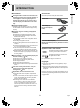
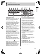
e00_l8hbe_xe_7.book Page 2 Tuesday, April 27, 2004 10:35 AM INTRODUCTION Accessories The digital video recorder records video from monitoring cameras to its internal hard disk, it can display the video being displayed on a monitor split into four or six screens, and it can also display recorded video in the same way. Check that you have all the parts shown below.
e00_l8hbe_xe_7.book Page 3 Tuesday, April 27, 2004 10:35 AM CONTENTS INTRODUCTION 1 BEFORE USE................................................. 5 2 NAMES AND FUNCTIONS OF PARTS ......... 7 Notes on handling the internal HDD ............... 5 Notes on installation locations ........................ 5 The hard disk and cooling fan are consumable components. ............................... 6 Important recordings ....................................... 6 Protection of the hard disk ..........................
e00_l8hbe_xe_7.book Page 4 Tuesday, April 27, 2004 10:35 AM CONTENTS 4 GENERAL SET............................................. 76 1 MENU CONFIGURATION AND OPERATIONS .............................................. 39 2 INITIAL SET ................................................. 43 Initial settings ................................................ 43 Setting the time ............................................. 43 Setting the summer time ............................... 43 External clock setting .......
e00_l8hbe_xe_7.book Page 5 Tuesday, April 27, 2004 10:35 AM 1 BEFORE USE Notes on handling the internal HDD Notes on replacing the HDD This digital video recorder uses an internal hard disk drive (HDD). Be sure to observe the following points carefully when operating, setting-up, or servicing the digital video recorder. Be sure to follow the correct procedure when replacing the HDD.
e00_l8hbe_xe_7.book Page 6 Tuesday, April 27, 2004 10:35 AM 1 BEFORE USE INTRODUCTION The hard disk and cooling fan are consumable components. If used in an ambient temperature of 25ºC, the hard disk should generally be replaced after 2 years; and the cooling fan after 3 years. These figures are intended as a general guideline only and should not be taken as a guarantee of component performance. The POWER indicator will flash if a problem occurs with the hard disk or fan. (JP.
e00_l8hbe_xe_7.
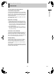
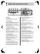
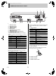
e00_l8hbe_xe_7.book Page 8 Tuesday, April 27, 2004 10:35 AM 2 NAMES AND FUNCTIONS OF PARTS 2 3 4 5 7 8 14 11 MENU 12 15 EXIT 13 23 16 PLAY/STOP C POWER FULL 1 ALARM FULL 2 3 4 LOCK 5 ALARM ZOOM 6 6 QUAD MULTI MON 2 OSD 9 12. [EXIT] button and indicator The [EXIT] button is used to exit the main menu or a submenu. When a menu is displayed, the indicator will turn off; when the menu is closed and the normal display is restored, the indicator will light up.
e00_l8hbe_xe_7.
e00_l8hbe_xe_7.book Page 10 Tuesday, April 27, 2004 10:35 AM 3 INSTALLATION AND CONNECTIONS INTRODUCTION This section describes how to connect the digital video recorder to video cameras and other devices. Be sure to read the instruction manuals for each connected device. z Improper connections can result in malfunction or the emission of smoke. z A separate power supply is required for operation of each camera.
e00_l8hbe_xe_7.book Page 11 Tuesday, April 27, 2004 10:35 AM 3 INSTALLATION AND CONNECTIONS Connecting SENSOR ALARM OUT terminals Connecting the power cord 1 The sensor alarm output terminals are used to relay alarm signals whenever one of the digital video recorder’s motion sensors is triggered. Normally in an open condition, a terminal adopts low condition when a sensor for the corresponding camera number has been triggered.
e00_l8hbe_xe_7.book Page 12 Tuesday, April 27, 2004 10:35 AM 1 PREPARING FOR USE (5) Picture quality display (JP.62,68) Displays the quality of the video that can be recorded on the hard disk. Set to “EN” (Enhanced) by default. Operation display area Whenever the power is turned on, the operation display area will be shown at the top of the monitor screen. This area indicates the date, time, picture quality, and other information needed for operation.
e00_l8hbe_xe_7.book Page 13 Tuesday, April 27, 2004 10:35 AM 1 PREPARING FOR USE 3 Changing the position of the operation display area 1 Press the [OSD] button several times. Turn the jog dial to select “1. LANGUAGE/CLOCK SET”, and then turn the shuttle dial clockwise. The cursor moves to “ENGLISH”. As the [OSD] button is pressed, the operation display area moves to a different location or is hidden.
e00_l8hbe_xe_7.book Page 14 Tuesday, April 27, 2004 10:35 AM 1 PREPARING FOR USE 4 Setting the time Turn the shuttle dial clockwise. “01” flashes (indicating the day). (Default: 01-01-2004 THU 00:00:00) Be sure to set the correct date and time as these settings are used during recording and searching. Example: Setting 8:30 on 22 May 2004 Press the [MENU] button. The MENU indicator lights up and the is displayed.
e00_l8hbe_xe_7.book Page 15 Tuesday, April 27, 2004 10:35 AM 1 PREPARING FOR USE The internal hard disk z If the memory allocations for the various hard disk recording areas are changed during a recording process, all stored recordings will be deleted and the hard disk will be initialized; accordingly, special care should be taken. For more details, refer to P.58. z In the case of certain hard disks, error may be present in the total hard disk capacity as displayed on menu screens.
e00_l8hbe_xe_7.book Page 16 Tuesday, April 27, 2004 10:35 AM 2 VIEWING VIDEO FROM A CAMERA [MULTI] button [SEQUENCE] button OPERATION [CAMERA SELECT] buttons [MON2] button [QUAD] button Viewing on a full screen Viewing on multiple screens Use the following procedure to display video from the connected cameras in split-screen format. Example: Selecting Camera 2 1 Press the No. 2 [CAMERA SELECT] button. Viewing on quad screens 1 The No.
e00_l8hbe_xe_7.book Page 17 Tuesday, April 27, 2004 10:35 AM 2 VIEWING VIDEO FROM A CAMERA Viewing on multi 6 screens 1 Setting automatic quad-screen selection 1 Press the [MULTI] button. The MULTI indicator lights up and the monitor display is divided in six. Press the [QUAD] button. The QUAD indicator lights up and the monitor display is divided in four.
e00_l8hbe_xe_7.book Page 18 Tuesday, April 27, 2004 10:35 AM 2 VIEWING VIDEO FROM A CAMERA Viewing on the monitor 2 Setting automatic full screen selection 1 When a monitor 2 is connected to the monitor 2 output terminal on the digital video recorder’s rear panel, this monitor can be used to view video from a single camera or to automatically scroll through video from all cameras, even if the main monitor is currently displaying video in split-screen format.
e00_l8hbe_xe_7.book Page 19 Tuesday, April 27, 2004 10:35 AM 3 RECORDING POWER indicator FULL indicator [REC/STOP] button Normal recording Timer recording Use the following procedure to record the monitored video for a preset length of time in the normal recording area. Recording will not be possible until a time has been set for the digital video recorder. Make sure to set the time. (JP.14) Use the following procedure to record the monitored video in the normal recording area.
e00_l8hbe_xe_7.book Page 20 Tuesday, April 27, 2004 10:35 AM 3 RECORDING POWER indicator [EXIT] button ALARM FULL indicator Alarm recording [TIMER] button When an alarm signal is detected z When an alarm signal is detected, “ALARM” flashes in the operation display and the alarm recording starts (indicated by “REC”). z Alarm video is recorded to the alarm recording area. z Whenever an alarm occurs, the number of alarms as indicated in the operation display is incremented.
e00_l8hbe_xe_7.book Page 21 Tuesday, April 27, 2004 10:35 AM 3 RECORDING Pre-alarm recording If an alarm is detected Pre-alarm recording is automatically ended and alarm recording starts. z “PRE” from the operation display area is replaced by “ALARM”, and “ALARM” starts to flash. Use the following procedure to record video from immediately before occurrence of an alarm. 1 Set pre-alarm recording. 01-01-04 00:00:00 REC REPEAT EN A ALARM 0000 Follow the instructions on P.68 set “7.
e00_l8hbe_xe_7.book Page 22 Tuesday, April 27, 2004 10:35 AM 4 PLAYBACK Use the procedures following procedure to play video stored in the normal recording area (during normal or timer recording). Normal recording area [PLAY/STOP] button POWER indicator Shuttle dial Playing video on a full screen 1 1 The PLAY/STOP indicator lights up, and “ ” appears in the operation display area. Video stored in the normal recording area is played back.
e00_l8hbe_xe_7.book Page 23 Tuesday, April 27, 2004 10:35 AM 4 PLAYBACK (3) Returning to normal playback. Turn the jog dial slightly clockwise to display “ ”. Enlarging the playback video 1 Press the [ZOOM] button during playback. Zoom indicator lights and a blue zoom frame appears in the center of the screen. z Audio will not be played during fast-forward, fastrewind, slow, reverse-slow, and reverse playback.
e00_l8hbe_xe_7.book Page 24 Tuesday, April 27, 2004 10:35 AM 4 3 PLAYBACK Turn the shuttle dial clockwise. Viewing still images The area enclosed by the zoom frame is magnified (by a factor of 2). 01-01-04 00:00:00 1 Press the [STILL] button during playback. The STILL indicator lights up and playback video is paused. The symbol “ ” appears in the operation display area.
e00_l8hbe_xe_7.book Page 25 Tuesday, April 27, 2004 10:35 AM 4 PLAYBACK Playing video on multiple screens Playing video on six screens 1 If you are recording video from a number of different cameras, the following procedures can be used to play the recorded video in multi-screen format. The MULTI indicator lights up and the monitor display is divided in six. Playing video on quad screens 1 Press the [MULTI] button during playback. MULTI Press the [QUAD] button during playback.
e00_l8hbe_xe_7.book Page 26 Tuesday, April 27, 2004 10:35 AM 5 SEARCHING FOR RECORDED VIDEO (1) ALARM SEARCH (JP.27) Lets you search and playback alarm video from the recording list. Images stored in the normal recording area, alarm recording area or archive area can be located by searching and can then be played back.Use one of the following five search methods locate the required video.
e00_l8hbe_xe_7.book Page 27 Tuesday, April 27, 2004 10:35 AM 5 SEARCHING FOR RECORDED VIDEO 3 Alarm search Use the following procedure to search and playback all video stored in the alarm recording area. If pre-alarm video is being recorded, playback will start from immediately before the alarm. 1 Turn the jog dial to move the cursor and select the video for playback. A preview of the selected alarm video is displayed in the preview screen.
e00_l8hbe_xe_7.book Page 28 Tuesday, April 27, 2004 10:35 AM 5 SEARCHING FOR RECORDED VIDEO z When playback is performed after an alarm search, the frame at the start and end of each alarm recording will be paused. Press the appropriate [ALARM] button to play the previous or next alarm recording. z You can use the front-panel buttons, the shuttle dial, and the jog dial to perform operations such as pause and fast-forward. z To leave search mode Press the [SEARCH] button. SEARCH indicator turns off.
e00_l8hbe_xe_7.book Page 29 Tuesday, April 27, 2004 10:35 AM 5 3 SEARCHING FOR RECORDED VIDEO 4 Turn the shuttle dial clockwise. After searching, the recording for the date and time settings is displayed in the preview screen. The
e00_l8hbe_xe_7.book Page 30 Tuesday, April 27, 2004 10:35 AM 5 SEARCHING FOR RECORDED VIDEO 4 Archive area search The selected image is displayed on the preview screen. Use the following procedure to playback video that has been stored in the archive area. 1 Turn the jog dial to select the video for playback. Press the [SEARCH] button while the digital video recorder is recording or stopped.
e00_l8hbe_xe_7.book Page 31 Tuesday, April 27, 2004 10:35 AM 5 2 SEARCHING FOR RECORDED VIDEO 5 Turn the jog dial to select “MOTION DETECTION SEARCH”, and then turn the shuttle dial clockwise. The screen is displayed. Turn the shuttle dial clockwise, and then turn the jog dial to select a camera number. (Selection example: 4) 6 Turn the shuttle dial clockwise. The cursor moves to “START PREVIEW”.
e00_l8hbe_xe_7.book Page 32 Tuesday, April 27, 2004 10:35 AM 5 SEARCHING FOR RECORDED VIDEO (2) Turn the shuttle dial clockwise to set a motion sensor. : ON, : OFF Set the motion sensor to use for searching. 1 Turn the shuttle dial clockwise while video is being displayed on the preview screen. (3) Use the jog dial in the same way to set sensors at other locations. OPERATION (1) Turn the jog dial to set the start date and time for motion sensing (i.e.
e00_l8hbe_xe_7.book Page 33 Tuesday, April 27, 2004 10:35 AM 5 5 SEARCHING FOR RECORDED VIDEO Turn the shuttle dial clockwise. The display returns to the screen. 6 Turn the jog dial to select “PREVIEW”. 7 Turn the shuttle dial clockwise. z By specifying a camera number (or channel) and performing “MOTION DETECTION SEARCH”, playback can be carried out for only the specified camera number.
e00_l8hbe_xe_7.book Page 34 Tuesday, April 27, 2004 10:35 AM 6 SAVING (COPYING) RECORDED VIDEO Use the procedures described below to copy important video stored in the normal recording area or the alarm recording area to the digital video recorder’s archive area, a CompactFlash card, or a Microdrive. Copying video to the hard disk’s archive area (JP.35) Copy Copy Archive area OPERATION Alarm recording area Normal recording area Copying video to a CompactFlash card or Microdrive (JP.
e00_l8hbe_xe_7.book Page 35 Tuesday, April 27, 2004 10:35 AM 6 SAVING (COPYING) RECORDED VIDEO 4 Copying video to the hard disk’s archive area Turn the jog dial to select “COPY TO”, and then turn the shuttle dial clockwise. “ARCHIVE AREA” starts to flash. [Settings] ( indicates the default setting) [PLAY/STOP] button Setting [STILL] button ARCHIVE AREA Shuttle dial COMPACT FLASH Description Video will be copied to the archive area. Video will be copied to a CompactFlash card.
e00_l8hbe_xe_7.book Page 36 Tuesday, April 27, 2004 10:35 AM 6 8 SAVING (COPYING) RECORDED VIDEO Turn the jog dial to select “SECONDS”. (2) When this procedure has been completed, “COPY FINISHED!” is displayed. OPERATION [Settings] ( indicates the default setting) Setting Description To cancel a copy operation The specified number of images after the PICTURES specified location will be copied. 9 SECONDS The specified duration in seconds after the specified location will be copied.
e00_l8hbe_xe_7.book Page 37 Tuesday, April 27, 2004 10:35 AM 6 2 SAVING (COPYING) RECORDED VIDEO 6 Pause playback on the image to be copied, and then press the [COPY] button. Turn the shuttle dial clockwise. “PICTURES” flashes. The screen is displayed. COPY 7 3 [Settings] ( indicates the default setting) Turn the jog dial to select “COPY TO”, and then turn the shuttle dial clockwise.
e00_l8hbe_xe_7.book Page 38 Tuesday, April 27, 2004 10:35 AM 6 SAVING (COPYING) RECORDED VIDEO (2) When this has been completed, “COPY FINISHED!” is displayed. z Playing video with audio that has been copied to a CompactFlash card video with audio can be played using DVR Viewer. For more details, refer to the “Manual for Remote Operation by Network Connection”.
e00_l8hbe_xe_7.book Page 39 Tuesday, April 27, 2004 10:35 AM 1 MENU CONFIGURATION AND OPERATIONS 3 [EXIT] button [MENU] button Turn the shuttle dial clockwise. The sub-menus appear. The cursor is positioned on the first setting item. Shuttle dial 4 Jog dial Turn the jog dial to select a sub-menu, and then turn the shuttle dial clockwise. The corresponding setting screen is displayed, and the cursor is positioned on the first item.
e00_l8hbe_xe_7.book Page 40 Tuesday, April 27, 2004 10:35 AM 1 MENU CONFIGURATION AND OPERATIONS Movement and confirmation in sub-menus and setting screens The jog dial and shuttle dial are used for movement and confirmation in sub-menus and setting screens. (2) (1) (3) To move the cursor Turn the jog dial. up or down SETTINGS (1) To move the cursor Turn the shuttle dial clockwise. (2) right or to confirm an item (3) To change a setting value Turn the jog dial.
e00_l8hbe_xe_7.book Page 41 Tuesday, April 27, 2004 10:35 AM 1 MENU CONFIGURATION AND OPERATIONS Main menu Sub menu Turn the jog dial to select the item to be set, and then turn the shuttle dial clockwise. Sub-menu configuration The following table indicates the sub-menus or setting screens displayed by selecting items from the . The [MENU] button can be used in any sub-menu to scroll through each of the sub-menus in sequence.
e00_l8hbe_xe_7.book Page 42 Tuesday, April 27, 2004 10:35 AM 1 MENU CONFIGURATION AND OPERATIONS Sub menu This sub-menu is used to make screen settings for monitoring. Setting item Settings or display content Specifies the positions of video from different cameras on the quad (1) MULTI SCREEN (JP.87) and multi 6 screens. (2) SEQUENCE SET (JP.89) Sets the switching interval for automatic camera selection.
e00_l8hbe_xe_7.book Page 43 Tuesday, April 27, 2004 10:35 AM 2 INITIAL SET [EXIT] button [MENU] button Main Menu Shuttle dial Jog dial Setting Initial settings The is used to make the following setting. Description Ref.
e00_l8hbe_xe_7.book Page 44 Tuesday, April 27, 2004 10:35 AM 2 3 INITIAL SET 7 Turn the jog dial to select “1. LANGUAGE/CLOCK SET”, and then turn the shuttle dial clockwise. Turn the shuttle dial clockwise. The cursor moves to the date/time at which to switch from standard time to summer time. The screen is displayed.
e00_l8hbe_xe_7.book Page 45 Tuesday, April 27, 2004 10:35 AM 2 INITIAL SET 10 Turn the jog dial to select the desired 3 day of the week, and then turn the shuttle dial clockwise. Turn the jog dial to select “1. INITIAL SET”, and then turn the shuttle dial clockwise. The screen is displayed. The cursor moves to the month. 11 Turn the jog dial to select the desired month, and then turn the shuttle dial clockwise. The cursor moves to the time.
e00_l8hbe_xe_7.book Page 46 Tuesday, April 27, 2004 10:35 AM 2 7 INITIAL SET 2 Turn the jog dial to set a time, and then turn the shuttle dial clockwise. (Example: 05:00) Turn the jog dial to select “1. INITIAL SET”, and then turn the shuttle dial clockwise. The screen is displayed. 3 8 Press the [EXIT] button. Turn the jog dial to select “2. CAMERA DETECT”, and then turn the shuttle dial clockwise.
e00_l8hbe_xe_7.book Page 47 Tuesday, April 27, 2004 10:35 AM 2 INITIAL SET 4 Setting camera titles Use the following procedure to set a unique title for each camera so that these titles can be displayed on-screen. Press the No. 3 [CAMERA SELECT] button. The video from Camera No. 3 is displayed on-screen. Titles can be up to 10 characters in length per camera. The following characters can be used. z Letters: A to Z z Numbers: 0 to 9 z Symbols: - : .
e00_l8hbe_xe_7.book Page 48 Tuesday, April 27, 2004 10:35 AM 2 8 9 INITIAL SET Repeat steps 5 and 6 to enter the remaining characters. Setting holidays Use the following procedure to set specific dates as holidays to have the operation for Sunday used on those days also. Dates such as national holidays and company off days should be set as holidays when you want those dates to have the same security as Sundays. When you have finished making settings, press the [EXIT] button.
e00_l8hbe_xe_7.book Page 49 Tuesday, April 27, 2004 10:35 AM 2 3 INITIAL SET 7 Turn the jog dial to select “4. HOLIDAY SET”, and then turn the shuttle dial clockwise. Press the [EXIT] button. The setting procedure is ended and the display returns to the normal screen. The default setting is all “-----”. The screen is displayed with the cursor positioned on “1”.
e00_l8hbe_xe_7.book Page 50 Tuesday, April 27, 2004 10:35 AM 2 INITIAL SET Setting time periods Operations during the specified time periods The following menu settings must be made to enable operation of the time periods. After completing these settings, be sure to then carry out timer setting.
e00_l8hbe_xe_7.book Page 51 Tuesday, April 27, 2004 10:35 AM 2 INITIAL SET 3 Timer period settings Example 1: Setting periods using TIME PERIOD A and TIME PERIOD B Turn the jog dial to select “5. TIME PERIOD SET”, and then turn the shuttle dial clockwise. The
e00_l8hbe_xe_7.book Page 52 Tuesday, April 27, 2004 10:35 AM 2 8 INITIAL SET 1 Turn the jog dial to set T2 (minutes) to “30” (minutes), and then turn the shuttle dial clockwise. “00:” from T3 flashes (indicating the hour). Repeat steps 4 through 7 to make hour and minute settings for T3 and T4. 9 Turn the jog dial to move the cursor to “SEQUENCE” within “SELECT TIME PERIOD”, and then turn the shuttle dial clockwise. “TIME PERIOD A” flashes.
e00_l8hbe_xe_7.book Page 53 Tuesday, April 27, 2004 10:35 AM 3 RECORD SET FULL indicator Main Menu ALARM FULL indicator [EXIT] button [MENU] button Shuttle dial Jog dial Settings for recording The is used to make the following settings. Setting 1 2 3 4 English Description Ref. 5 Sets program recording for cameras P.63 6 Makes timer settings so that operations can be started at a specified time or on a specified day. P.
e00_l8hbe_xe_7.book Page 54 Tuesday, April 27, 2004 10:35 AM 3 RECORD SET (1) When the number of cameras detected using “CAMERA DETECT” is greater or less than the number of cameras previously stored in the digital video recorder. (2) When the setting for “PRE-ALARM RECORDING” from the screen is changed. (3) When menu settings are loaded from a CompactFlash card. (4) When a new easy setup setting operation is carried out.
e00_l8hbe_xe_7.book Page 55 Tuesday, April 27, 2004 10:35 AM 3 7 RECORD SET Turn the shuttle dial clockwise. [Settings] ( indicates the default setting) Setting “OFF” flashes. Description BASIC (BA) 15 kB NORMAL (NO) 22 kB ENHANCED(EN) 30 kB FINE (FI) 42 kB SUPER FINE (SF) 50 kB 10 Set “AUDIO RECORDING”. 8 (Example: ON) To activate timer operation, turn the jog dial to select “ON”, and then turn the shuttle dial clockwise. The cursor moves to “START”.
e00_l8hbe_xe_7.book Page 56 Tuesday, April 27, 2004 10:35 AM 3 RECORD SET 13 Press the [EXIT] button. 5 The setting procedure is ended and the display returns to the normal screen. “60.00” flashes. Turn the shuttle dial clockwise. EXIT z The recording rate is automatically calculated based on recording settings and the number of connected cameras, and this is indicated by “REC RATE”. All cameras will record at this rate. If a valid figure cannot be calculated, “ERROR!” will be displayed.
e00_l8hbe_xe_7.book Page 57 Tuesday, April 27, 2004 10:35 AM 3 RECORD SET The following settings are carried out using the shuttle dial and jog dial. z Vertical cursor movement: Turn the jog dial. z Cursor movement to the right: Turn the shuttle dial clockwise. z Modification of values: Turn the shuttle dial clockwise, and then with the setting value flashing, turn the jog dial. z Confirmation of values: Turn the shuttle dial clockwise.
e00_l8hbe_xe_7.book Page 58 Tuesday, April 27, 2004 10:35 AM 3 RECORD SET Total capacity following hard disk expansion. Default hard disk settings By default, the normal recording area is set to 80%; the alarm recording area is set to 19%; and the archive area is set to 1%. The maximum capacity of the archive area is 10 GB.
e00_l8hbe_xe_7.book Page 59 Tuesday, April 27, 2004 10:35 AM 3 RECORD SET The following settings are carried out using the shuttle dial and jog dial. z Vertical cursor movement: Turn the jog dial. z Cursor movement to the right: Turn the shuttle dial clockwise. z Modification of values: Turn the shuttle dial clockwise, and then with the setting value flashing, turn the jog dial. z Confirmation of values: Turn the shuttle dial clockwise. 3 Set “ALARM RECORDING AREA” to 49%.
e00_l8hbe_xe_7.book Page 60 Tuesday, April 27, 2004 10:35 AM 3 2 RECORD SET 6 Turn the jog dial to select “2. RECORDING AREA SET” from the screen, and then turn the shuttle dial clockwise. Press the [EXIT] button. The setting procedure is ended and the display returns to the normal screen. EXIT The screen is displayed.
e00_l8hbe_xe_7.book Page 61 Tuesday, April 27, 2004 10:35 AM 3 2 RECORD SET 6 Turn the jog dial to select setting (OFF, for example), and then turn the shuttle dial clockwise. The setting procedure is ended and the display returns to the normal screen. EXIT “REMAINING DISK WARNING” changes to “1%” from “**”. [Settings] ( indicates the default setting) Setting Description OFF Recording is stopped when the normal recording area becomes full.
e00_l8hbe_xe_7.book Page 62 Tuesday, April 27, 2004 10:35 AM 3 3 4 RECORD SET 3 Turn the shuttle dial clockwise. Press the [EXIT] button. Turn the jog dial to select “4. NORMAL REC MODE SET”, and then turn the shuttle dial clockwise. The screen is displayed. The setting procedure is ended and the display returns to the normal screen.
e00_l8hbe_xe_7.book Page 63 Tuesday, April 27, 2004 10:35 AM 3 RECORD SET Setting program recording z Audio recording can only be specified when “REC RATE” is between A 60.00 and A 1.00 FPS. z When set to “ON”, the letter “A (indicating that audio will be recorded)” is displayed in front of the recording rate. As both video and audio will be stored in the normal recording area, this area’s overall capacity will reduce accordingly.
e00_l8hbe_xe_7.book Page 64 Tuesday, April 27, 2004 10:35 AM 3 2 RECORD SET 6 Turn the jog dial to select “5. PROGRAM REC SET”, and then turn the shuttle dial clockwise. The screen is displayed with the cursor positioned on “PROGRAM”. Turn the jog dial to select a recording rate (3.75, for example), and then turn the shuttle dial clockwise. Camera No. 1 is now set to record at a rate of 3.75. The cursor moves to “02”. Valid recording rates 30*, 15, 7.5, 3.75, 1.875, 1.0, 0.500, 0.
e00_l8hbe_xe_7.book Page 65 Tuesday, April 27, 2004 10:35 AM 3 RECORD SET Timer settings z The settings made using are used to set quality and audio recording for timer recording. (JP.62) z Ensure that start and end times are input using 24-hour notation. z If the start and end times are on different days (i.e., midnight is included), a “T” will be displayed to the left of the end time. Use the following procedures to set recording start and stop times using the timer function.
e00_l8hbe_xe_7.book Page 66 Tuesday, April 27, 2004 10:35 AM 3 4 RECORD SET Turn the jog dial to set “SUN” to “DLY”, and then turn the shuttle dial clockwise. z If timer settings overlap, recording is performed in the following sequence. Each daily reservation → DLY → EXT Priority (high) ←−−−−−−−−−−−−→ (low) z If a reservation for a particular day overlaps with a daily reservation, priority is given to that with the earliest start time.
e00_l8hbe_xe_7.book Page 67 Tuesday, April 27, 2004 10:35 AM 3 2 RECORD SET Make settings in the “WEEK” and “START” columns. Timer recording using an external timer Use the following procedure to control the start and end of recording in response to signals received via the EXT TIMER ON terminal on the rear of the digital video recorder. (1) Turn the jog dial to change “SAT” to “MON”, and then turn the shuttle dial clockwise. “--” (time) under “START” flashes.
e00_l8hbe_xe_7.book Page 68 Tuesday, April 27, 2004 10:35 AM 3 5 RECORD SET 2 Turn the jog dial to change “OFF” to “ON”, and then turn the shuttle dial clockwise. The screen is displayed. The cursor moves to line 1. EXT 6 ***** ***** Turn the jog dial to select “7. ALARM REC MODE SET”, and then turn the shuttle dial clockwise. OFF 5FPS The cursor moves to “ALARM RECORDING”. ON Press the [EXIT] button. The setting is completed and turns to normal screen.
e00_l8hbe_xe_7.book Page 69 Tuesday, April 27, 2004 10:35 AM 3 5 RECORD SET 7 Set “PICTURE QUALITY”. SET “ALARM INTERLEAVE” [Settings] ( indicates the default setting) Setting Description BASIC (BA) 15 kB NORMAL (NO) 22 kB ENHANCED(EN) 30 kB FINE (FI) 42 kB SUPER FINE (SF) 50 kB [Settings] ( indicates the default setting) Setting Description SW Recording is switched between camera video including an alarm and video from all connected cameras.
e00_l8hbe_xe_7.book Page 70 Tuesday, April 27, 2004 10:35 AM 3 RECORD SET 2 When alarm recording settings have been completed Press the [EXIT] button. EXIT Turn the jog dial to change “OFF” to “ON”, and then turn the shuttle dial clockwise. A message appears indicating automatic rate adjustment. “NO” flashes. The setting procedure is ended and the display returns to the normal screen. “ALARM” appears in the operation display area. When an alarm occurs, the number of alarms is displayed.
e00_l8hbe_xe_7.book Page 71 Tuesday, April 27, 2004 10:35 AM 3 6 RECORD SET Turn the jog dial to set “DURATION” (10 SEC for example), and then turn the shuttle dial clockwise. Setting the alarm trigger Use this setting to indicate how alarms are to be detected. 1 (Default setting: 1 MIN) The cursor moves to “ALARM TRIGGER”. Turn the jog dial to select “ALARM TRIGGER”, and then turn the shuttle dial clockwise. “ALARM” flashes in the “ALARM TRIGGER” field.
e00_l8hbe_xe_7.book Page 72 Tuesday, April 27, 2004 10:35 AM 3 RECORD SET 2 Setting the motion sensors Use the following procedure to set motion sensor on video from each camera so that alarms can be detected. Turn the jog dial select “MOTION SENSOR”, and then turn the shuttle dial clockwise. The motion sensor screen is displayed. (1) (2) (3) (4) (5) The cursor (blue) is displayed at the top left position.
e00_l8hbe_xe_7.book Page 73 Tuesday, April 27, 2004 10:35 AM 3 RECORD SET [Settings] ( indicates the default setting) Setting z All sensors on the same line as the cursor can be modified simultaneously by pressing the [MENU RESET] button. (A → B → -) 8 OFF 1 to10 Turn the jog dial to move the cursor to “T-1”, and then turn the shuttle dial clockwise. Motion sensing is not carried out. Motion sensing is carried out. Lower values correspond to higher sensitivities.
e00_l8hbe_xe_7.book Page 74 Tuesday, April 27, 2004 10:35 AM 3 RECORD SET 2 z Motion sensor positions are common for T-1 through T-4, and different settings cannot be made. Turn the jog dial to select “8. ALARM OPERATION SET”, and then turn the shuttle dial clockwise. The screen is displayed with the cursor positioned on “ALARM RETRIGGER”. 15 Turn the shuttle dial counter-clockwise. Motion sensor settings are confirmed and the screen is displayed once again.
e00_l8hbe_xe_7.book Page 75 Tuesday, April 27, 2004 10:35 AM 3 RECORD SET Setting alarm display 1 z After an alarm duration has ended, the display returns to the screen prior to alarm input. Turn the jog dial to select “MAIN MON. DISPLAY”, and then turn the shuttle dial clockwise. 4 “FULL” starts to flash for “MAIN MON. DISPLAY”. Turn the shuttle dial clockwise and turn the jog dial to set “MON.2 DISPLAY” (ON/OFF), and then turn the shuttle dial clockwise. The cursor moves to “ALARM RETRIGGER”.
e00_l8hbe_xe_7.book Page 76 Tuesday, April 27, 2004 10:35 AM 4 GENERAL SET [EXIT] button Main menu [MENU] button Shuttle dial Jog dial Setting General settings The is used to make the following settings. 6 Description Ref. Lets you make settings when using RS-485. P.85 SETTINGS Setting data display Setting 1 2 Description Use the following procedure to remove the date, time, or other information from the operation display area.
e00_l8hbe_xe_7.book Page 77 Tuesday, April 27, 2004 10:35 AM 4 3 GENERAL SET 6 Turn the shuttle dial clockwise. “ON” for the (1) “DATE” flashes. This can be set to “OFF” turning the jog dial to remove the date from the operation display area. 4 The setting procedure is ended and the display returns to the normal screen. EXIT Turn the shuttle dial clockwise. The cursor moves to the time entry. The following settings are carried out using the shuttle dial and jog dial.
e00_l8hbe_xe_7.book Page 78 Tuesday, April 27, 2004 10:35 AM 4 GENERAL SET 3 Setting the buzzer “OFF” flashes for “ALARM”. Use the following procedure to set a warning buzzer to sound for alarms or when hard disk space becomes insufficient. 1 Turn the shuttle dial clockwise. 4 Turn the jog dial to display “ON”, and then turn the shuttle dial clockwise. Press the [MENU] button, turn the jog dial to select “3. GENERAL SET”, and then turn shuttle dial clockwise.
e00_l8hbe_xe_7.book Page 79 Tuesday, April 27, 2004 10:35 AM 4 GENERAL SET Setting the security lock Setting the administrator password Passwords comprise between 4 and 8 alphanumeric characters. Characters that can be entered in passwords: 0 to 9, A to Z Use the procedures described below to set a passwords and to prevent unauthorized users from operating the digital video recorder. If a button is pressed while the security lock is in operation, a buzzer will be sounded.
e00_l8hbe_xe_7.book Page 80 Tuesday, April 27, 2004 10:35 AM 4 GENERAL SET 3 z To set a 4-digit password Turn the shuttle dial clockwise when “-” for the fifth character is flashing. 7 Turn the jog dial clockwise. The second password entry bar “-” flashes. Turn the jog dial to display “B”. Use the same procedure as for the administrator password to set “123456”. Following this, turn the shuttle dial clockwise. 4 The cursor moves to “OFF” (flashing). Following this, turn the shuttle dial clockwise.
e00_l8hbe_xe_7.book Page 81 Tuesday, April 27, 2004 10:35 AM 4 3 GENERAL SET 4 Press the [EXIT] button. Turn the shuttle dial clockwise. The security lock is cancelled and the display returns to the normal screen. The setting procedure is ended and the display returns to the normal screen. EXIT z If an administrator password was entered, the security lock is cancelled and the indicator is turned off.
e00_l8hbe_xe_7.book Page 82 Tuesday, April 27, 2004 10:35 AM 4 3 GENERAL SET Turn the shuttle dial clockwise. set, the recording rate is controlled automatically (i.e., set to half of the normal value) and the appropriate care must be taken. z PLAYBACK DRIVE: This parameter is used together with “MIRRORING” and it indicates which of the two hard disks is to be used to provide recordings for playback. z If a playback problem occurs while mirroring is turned on, change the hard disk used for playback.
e00_l8hbe_xe_7.book Page 83 Tuesday, April 27, 2004 10:35 AM 4 GENERAL SET 4 z Connecting to an intranet (using a hub) The cursor moves to “NETWORK STATUS”. Main Monitor 1 2 3 4 Turn the jog dial to set to “ON (NETWORK)” or “ON (DVR)”, and then turn the shuttle dial clockwise. Monitor (sold separately) Ethernet switching hub PC 5 A straight-type LAN cable must be used here.
e00_l8hbe_xe_7.book Page 84 Tuesday, April 27, 2004 10:35 AM 4 GENERAL SET z Network control is only possible when “NETWORK CONTROL” has been set to “ON”. z In order to prevent network control while the digital video recorder is connected to a network, set “NETWORK CONTROL” to “OFF”. When connecting the digital video recorder to a network, check the following settings with the network administrator.
e00_l8hbe_xe_7.book Page 85 Tuesday, April 27, 2004 10:35 AM 4 3 GENERAL SET Enter the password using the shuttle dial and jog dial. Setting RS-485 Use the following procedure to make RS-485 settings. Connect the digital video recorder's RS-485 (A, B) control terminals on the rear panel to the system controller or similar device. (1) Turn the jog dial to select “A” and then turn the shuttle dial clockwise. (2) The second entry item “1” flashes.
e00_l8hbe_xe_7.book Page 86 Tuesday, April 27, 2004 10:35 AM 4 GENERAL SET 6 [Settings] ( indicates the default setting.) Setting DATA SPEED 4 Description 2400, 4800, 9600, 19200 Turn the shuttle dial clockwise and turn the jog dial to set “ADDRESS”, and then turn the shuttle dial clockwise. Turn the shuttle dial clockwise and turn the jog dial to set “STATUS INFO”, and then turn the shuttle dial clockwise. The cursor moves to “ALARM INFO”.
e00_l8hbe_xe_7.book Page 87 Tuesday, April 27, 2004 10:35 AM 5 SCREEN SET [EXIT] button Main Menu [MENU] button Shuttle dial Jog dial 2 Setting quad and multi 6 display Turn the shuttle dial clockwise. “NORMAL” flashes for “1. MULTI SCREEN”. Use the following procedure to change the display positions for cameras in quad and multi 6 screens. 01 02 05 03 01 06 04 01 02 02 04 05 03 06 01 02 3 z Each camera can only be displayed in one position on any screen.
e00_l8hbe_xe_7.book Page 88 Tuesday, April 27, 2004 10:35 AM 5 5 SCREEN SET Turn the shuttle dial clockwise, and then turn the jog dial to select “05”. Setting multi 6 positions Example: Displaying Camera No. 6 in multi 6 position 01 (for multi 6 display) “05” flashes. 6 Turn the shuttle dial clockwise. 1 “01” changes to “05”. Turn the jog dial to select “1. MULTI SCREEN”, and then turn the shuttle dial clockwise. “NORMAL” flashes.
e00_l8hbe_xe_7.book Page 89 Tuesday, April 27, 2004 10:35 AM 5 5 SCREEN SET Turn the jog dial to set “01”, and then turn the shuttle dial clockwise. Setting the period and monitors for automatic screen selection “06” changes to “01” and vice versa. Turn the shuttle dial counter-clockwise to return to the screen. Use the following procedure to scroll through video from all cameras using a specified period.
e00_l8hbe_xe_7.book Page 90 Tuesday, April 27, 2004 10:35 AM 5 4 SCREEN SET Press the [EXIT] button. Setting the main monitor and monitor 2 The setting procedure is ended and the display returns to the normal screen. Example: Specifying a monitor to display each camera’s video at the set period (as indicated by TIME PERIOD A and TIME PERIOD B). EXIT 1 Make timer settings for “TIME PERIOD A” and “TIME PERIOD B” from
e00_l8hbe_xe_7.book Page 91 Tuesday, April 27, 2004 10:35 AM 5 4 SCREEN SET 9 Turn the shuttle dial clockwise. “T-1” starts to flash for the time period. Use the same procedure to set the remaining channels. 10 Press the [EXIT] button. The setting procedure is ended and the display returns to the normal screen. EXIT 5 z When setting a number of time periods together, use the jog dial to move the cursor to the next period after completing step 9, and repeat the process from step 4.
e00_l8hbe_xe_7.book Page 92 Tuesday, April 27, 2004 10:35 AM 5 SCREEN SET 4 Setting masks Use the following procedure to set video from a specific camera (including playback video) to be masked by a gray pattern when it is not to be shown on a monitor screen. Turn the jog dial to select “ON”, and then turn the shuttle dial clockwise. The cursor moves to “MASK SET”. 01 5 04 The screen is displayed.
e00_l8hbe_xe_7.book Page 93 Tuesday, April 27, 2004 10:35 AM 5 8 SCREEN SET Turn the jog dial clockwise or counterclockwise to move the cursor to channel to be changed, and then turn the shuttle dial clockwise. z When setting a number of time periods together, use the jog dial to move the cursor to the next period after completing step 10, and repeat the process step 6 through 10. z The time period for “T-1” through “T-4” changes to that of “TIME PERIOD A” or “TIME PERIOD B” on P.50.
e00_l8hbe_xe_7.book Page 94 Tuesday, April 27, 2004 10:35 AM 5 3 SCREEN SET Press the [CAMERA SELECT] button for the camera whose color level is to be set, and then turn the shuttle dial clockwise. “AUTO” flashes. Turn the jog dial to select a “COLOR LEVEL” (AUTO or 1 through 10), and then turn the shuttle dial clockwise. SETTINGS 4 • AUTO: Camera levels are adjusted automatically. (Default value) • 1 to 10: Manual adjustment to one of 10 levels.
e00_l8hbe_xe_7.book Page 95 Tuesday, April 27, 2004 10:35 AM 6 POWER FAILURE/USED TIME Main Menu [EXIT] button [MENU] button Shuttle dial Jog dial 2 Use the following procedure to check the date and time of power failures, the amount of hard disk operation time, and the amount of power-on time. 1 The display returns to the normal screen. EXIT Press the [MENU] button and turn the select “5. POWER FAILURE/USED TIME”, and then turn the shuttle dial clockwise.
e00_l8hbe_xe_7.book Page 96 Tuesday, April 27, 2004 10:35 AM 7 INITIALIZED RECORD [EXIT] button Main menu [MENU] button Shuttle dial Jog dial 2 Use the following procedure to display the eight most recent entries in the initialization and re-recording log for the hard disk. The display returns to the normal screen. SETTINGS 1 Press the [EXIT] button. EXIT Press the [MENU] button and turn the jog dial to select “6. INITIALIZED RECORD”, and then turn the shuttle dial clockwise.
e00_l8hbe_xe_7.book Page 97 Tuesday, April 27, 2004 10:35 AM 8 COPY MENU SETTINGS Main Menu [EXIT] button [MENU] button Shuttle dial Jog dial 2 Use the following procedure to save menu settings on a CompactFlash card or to load settings from a CompactFlash card back into the digital video recorder. These functions make it easy to use the same settings on a number of different hard disk digital recorders. 1 Turn the jog dial to select “YES”, and then turn the shuttle dial clockwise.
e00_l8hbe_xe_7.book Page 98 Tuesday, April 27, 2004 10:35 AM 8 COPY MENU SETTINGS Loading settings from a CompactFlash card When copying recording area settings Use the following procedure to copy recording area settings. 1 Use the following procedure to load menu settings saved on a CompactFlash card back into the digital video recorder. Turn the jog dial to select “COPY RECORDING AREA SETTINGS”, and then turn the shuttle dial clockwise. “NO” flashes.
e00_l8hbe_xe_7.book Page 99 Tuesday, April 27, 2004 10:35 AM 1 INTERFACE SPECIFICATIONS RS-485 specifications RS-485 termination switch settings Data format Termination settings Mode Asynchronous Character length 8 bits Data transmission speed 2400, 4800, 9600, 19200 bps Parity check None Stop bit 1 bit When connecting multiple devices, you must make termination settings on both end devices. z Set the RS-485 termination switch of both end devices to ON.
e00_l8hbe_xe_7.book Page 100 Tuesday, April 27, 2004 10:35 AM 1 INTERFACE SPECIFICATIONS DVR/VCR command table The table below shows the commands supported by the digital video recorder.
e00_l8hbe_xe_7.
e00_l8hbe_xe_7.book Page 102 Tuesday, April 27, 2004 10:35 AM 2 SPECIFICATIONS Dimensions 349 OTHER 364.
e00_l8hbe_xe_7.book Page 103 Tuesday, April 27, 2004 10:35 AM 2 SPECIFICATIONS Table of recording rate and times This products’s recording time can be changed by modifying the recording rate and the recording picture quality. The following table provides reference values for picture quality and recording rate in a situation where video is recorded to the normal recording area of this product’s hard disk.
e00_l8hbe_xe_7.book Page 104 Tuesday, April 27, 2004 10:35 AM 2 SPECIFICATIONS Example: After expansion to 300 GB (100%-usage) Recording rate FPS (field/sec) BASIC 15kB NORMAL 22kB Recording time ENHANCED 30kB FINE 42kB SUPER FINE 50kB 60.00 30.00 20.00 15.00 10.00 7.50 6.00 5.00 4.29 3.75 3.33 3.00 2.73 2.31 2.00 1.67 1.43 1.25 1.11 1.00 0.50 0.33 0.25 0.20 0.10 0.05 0.
e00_l8hbe_xe_7.book Page 105 Tuesday, April 27, 2004 10:35 AM 2 SPECIFICATIONS Table of recording rate settings Normal recording rate Display sequence Recording rate FPS (field/sec) 1 60.00 (Note1, 2) 2 30.00 3 20.00 4 Alarm recording rate Display sequence Pre-alarm recording rate Recording rate FPS (field/sec) Display sequence 1 30.00 1 FPS (field/sec) 30.00 2 20.00 2 20.00 3 15.00 3 15.00 15.00 4 10.00 4 10.00 5 10.00 5 7.50 5 7.50 6 7.50 6 6.00 6 6.00 7 6.
e00_l8hbe_xe_7.book Page 106 Tuesday, April 27, 2004 10:35 AM 2 SPECIFICATIONS Table of pre-alarm recording times This table indicates recording times for pre-alarm recording, and it should be used when this type of recording is being carried out. Recording rate FPS (field/sec) 3s (3s) Recording time (Display of time on menu screens s: seconds m: minutes) 5s 10s 20s 40s 60s 120s 180s 240s 300s 500s (5s) (10s) (20s) (40s) (1m) (2m) (3m) (4m) (5m) (10m) 900s (15m) OTHER 30.00 20.00 15.00 10.00 7.50 6.
e00_l8hbe_xe_7.book Page 107 Tuesday, April 27, 2004 10:35 AM 3 English MENU SETTING SEQUENCE INITIAL SET (→P.43) RECORD SET (→P.53) LANGUAGE/CLOCK SET (→P.43) EASY SETUP (→P.53) RECORDING DURATION BASE (→P.54) CAMERA DETECT (→P.46) RECORDING AREA SET (→P.57) REC RATE BASE (→P.56) TITLE SET (→P.47) RECORDING CONDITIONS SET (→P.60) TIMER SET (→P.65) HOLIDAY SET (→P.48) NORMAL REC MODE SET (→P.62) ALARM REC MODE SET (→P.68) MOTION SENSOR SET (→P.72) TIME PERIOD SET (→P.
e00_l8hbe_xe_7.book Page 108 Tuesday, April 27, 2004 10:35 AM 3 MENU SETTING SEQUENCE GENERAL SET (→P.76) SCREEN SET (→P.87) POWER FAILURE/USED TIME (→P.95) QUAD POSITION SET MENU (→P.87) BUZZER SET (→P.78) MULTI 6 POSITION SET MENU (→P.88) SECURITY LOCK SET (→P.79) MAIN/MON2 MONITOR SET (→P.90) HDD SET (→P.81) MASK SET (→P.92) NETWORK SET (→P.82) COLOR LEVEL SET (→P.93) COPY MENU SETTINGS (→P.97) OTHER DISPLAY SET (→P.76) INITIALIZED RECORD (→P.96) RS-485 SET (→P.
e00_l8hbe_xe_7.book Page 109 Tuesday, April 27, 2004 10:35 AM INDEX A K Administrator ..................................................................79 ALARM FULL indicator ....................................................7 ALARM indicator ..............................................................7 ALARM OPERATION SET ............................................74 ALARM PRIORITY ........................................................75 Alarm recording ..........................................
e00_l8hbe_xe_7.book Page 110 Tuesday, April 27, 2004 10:35 AM INDEX Setting normal recording ................................................62 Setting program recording .............................................63 Setting quad positions ...................................................87 Setting recording conditions ..........................................60 Setting the color level ....................................................93 Setting time periods .........................................
e00_l8hbe_xe_7.