e00_l8hbc_hd_6.
e00_l8hbc_hd_6.book Page 1 Wednesday, July 30, 2003 2:34 PM PRECAUTION WARNING: TO REDUCE THE RISK OF FIRE OR ELECTRIC SHOCK, DO NOT EXPOSE THIS APPLIANCE TO RAIN OR OTHER MOISTURE. To avoid electrical shock, do not open the cabinet. Refer servicing to qualified personnel only. If the power supply cord (AC power cord) of this appliance is damaged, it must be replaced. Return to a SANYO Authorised Service Centre for replacement of the cord.
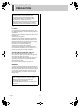
e03_l8hbc_hd_6.fm Page 2 Thursday, July 31, 2003 2:51 PM INTRODUCTION Main features Accessories This digital video recorder can be used to store images recorded by four monitoring cameras onto its built-in hard disk. Check that you have all the parts below. Power cord Large-capacity (120 GB or 240 GB) hard disk. Eliminates laborious tape replacement, and offers a long continuous recording time of at least 672 hours (240 GB; standard image quality).
e00_l8hbc_hd_6.book Page 3 Wednesday, July 30, 2003 2:34 PM CONTENTS INTRODUCTION 1 BEFORE USE................................................. 5 2 NAMES AND FUNCTIONS OF PARTS ......... 7 Notes on handling internal hard disk drive components .................................................... 5 Conditions to avoid ......................................... 5 The hard disk and cooling fan are expendable items. .............................................................. 5 Installation conditions.......
e00_l8hbc_hd_6.book Page 4 Wednesday, July 30, 2003 2:34 PM CONTENTS 4 DISPLAY SET............................................... 40 MENU CONFIGURATION AND OPERATIONS .............................................. 23 screen setting items.......... 40 Settings ......................................................... 40 5 BUZZER SET................................................ 41 screen setting items........... 41 Settings ....................................................
e00_l8hbc_hd_6.book Page 5 Wednesday, July 30, 2003 2:34 PM 1 BEFORE USE Notes on handling internal hard disk drive components In addition, use a method of transportation that minimizes the vibration. If the HDD becomes damaged, handle the unit and the damaged HDD that has been removed in order for it to be replaced carefully to prevent the problem from being aggravated until as the nature of the problem can be checked and analyzed. This unit has a built-in hard disk drive (HDD).
e05_l8hbc_hd_6.fm Page 6 Thursday, July 31, 2003 2:51 PM 1 BEFORE USE The [MENU] button is disabled when the unit is connected to a PC (VA-SW804/VA-SW80LITE). When the [MENU] button is operative, operations from the PC are disabled. Hard disk protection The hard disk is checked automatically at power ON. If a hard disk problem is found, the POWER indicator flashes. To initialize the disk or save images stored on the disk, contact a Sanyo service centre.
e00_l8hbc_hd_6.book Page 7 Wednesday, July 30, 2003 2:34 PM 2 NAMES AND FUNCTIONS OF PARTS Front panel 1 2 1 POWER 2 3 3 4 QUAD/ SEQUENCE AUDIO 8 CUE EXIT/OSD 1. USB 14 15 16 17 18 POWER indicator (JP. 10) 11. 12. CHANNEL buttons and indicators 13. 14. [MENU] button and indicator 15. [ 16. ] button 17. ] button 18. [CUE] button 19. 20. [EXIT/OSD] button (JP. 23) [STILL] button USB terminal (JP. 48) [REC/STOP] button and indicator Starts normal recording.
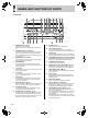
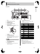
e00_l8hbc_hd_6.book Page 8 Wednesday, July 30, 2003 2:34 PM 2 NAMES AND FUNCTIONS OF PARTS Rear panel 2 3 AUDIO IN 3 5 LAN 1 4 4 INTRODUCTION 1 1 2 VIDEO 3 4 IN 2 1 2 3 4 OUT ALL RESET OUT MONITOR OUT RS-485 TV SYSTEM TERMINATE ON NTSC OFF PAL 1 2 3 4 5 6 7 8 9 10 11 12 13 14 15 16 17 18 19 AC IN 6 7 1. FAN 2. AUDIO IN terminals (4 channels) 3. AUDIO OUT terminal 4. LAN terminal (JP. 45) 5. VIDEO IN terminals (4 channels) 6. Power cord holder 8 9 10 11 12 11.
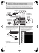
e00_l8hbc_hd_6.book Page 9 Wednesday, July 30, 2003 2:34 PM 3 INSTALLATION AND CONNECTIONS This section describes how to connect the digital video recorder to the CCTV camera and other devices. Be sure to read the instruction manuals for each connected device. Make connections carefully. Improper connections can cause smoke or malfunctions. Basic connections The connections for cameras (4), TV monitor (1), microphone and PC are shown below.
e05_l8hbc_hd_6.fm Page 10 Thursday, July 31, 2003 2:51 PM 3 INSTALLATION AND CONNECTIONS (1) Push in the lock pin with a flat-blade screwdriver. (2) Insert the cable. (3) Pull out the lock pin with a flat-blade screwdriver. The cable is now fixed in place.
e00_l8hbc_hd_6.book Page 11 Wednesday, July 30, 2003 2:34 PM 1 SCREEN DISPLAY AND POSITION (6) Time display (JP. 14) “00:00:00” is displayed when you turn the power ON for the first time. The digital video recorder uses the date and time to manage recording and playback points. At power ON, the operation display area appears at the top of the monitor screen.The operation display area shows the date/time, image quality, remaining time, and other information needed for operations.
e00_l8hbc_hd_6.book Page 12 Wednesday, July 30, 2003 2:34 PM 1 SCREEN DISPLAY AND POSITION 1 Changing the position of the operation display Press the [QUAD/SEQUENCE] button. The image from each channel is displayed sequentially in single screens. Under the default settings, the channel switches automatically every 1 second. Press the [EXIT/OSD] button repeatedly. Pressing the [EXIT/OSD] button repeatedly lets you move or erase the operation display area.
e00_l8hbc_hd_6.book Page 13 Wednesday, July 30, 2003 2:34 PM 2 SETTING THE LANGUAGE/CLOCK [MENU] button [ ] button [ ] button This section describes how to set the language displayed on the monitor and how to set the digital video recorder’s internal clock. (1) LANGUAGE (2) CLOCK SET 1 Setting Description ENGLISH Sets the language to English. ] button To change the language 3 [Settings] ( indicates default setting.
e00_l8hbc_hd_6.book Page 14 Wednesday, July 30, 2003 2:34 PM 2 SETTING THE LANGUAGE/CLOCK 4 Setting the time Press the [ ] button. “01” (indicating the day) flashes. (Default setting: 01-01-2003 WED 00:00:00) Be sure to set the correct date and time. The digital video recorder stores the times of recordings for use in operations such as playback and search/playback. Example: Setting 20 May 2003, 8:30 5 Press the [MENU] button.
e00_l8hbc_hd_6.book Page 15 Wednesday, July 30, 2003 2:34 PM 3 NORMAL RECORDING/TIMER RECORDING [TIMER] button [REC/STOP] button FULL indicator Normal recording Timer recording Follow the steps below to record the monitored image onto the hard disk. Follow the steps below to record the monitored image onto the hard disk at the set time. 1 z When using the recorder for the first time, check that the TV SYSTEM selector switch on the rear panel is set to “PAL” correctly.
e00_l8hbc_hd_6.book Page 16 Wednesday, July 30, 2003 2:34 PM 4 ALARM RECORDING ALARM indicator FULL indicator Follow the steps below to have the digital video recorder record an alarm image only when alarm input is detected. z Check that the cable of the device required for alarms is connected to the ALARM terminal. (JP. 8) 3 z When the motion sensor is set, an alarm image is recorded when a moving subject is detected. (JP.
e00_l8hbc_hd_6.book Page 17 Wednesday, July 30, 2003 2:34 PM 5 NORMAL RECORDING/TIMER RECORDING PLAYBACK Follow the steps below to play back images recorded on the hard disk. Playback while fast-forwarding/rewinding Playback [ ] button [ ] button [ ] button [PLAY/STOP] button [ 1 When you press the [ ] button, appears in the operation display, and the playback fast-forwards at 7.5 times the normal playback speed.
e06_l8hbc_hd_6.fm Page 18 Wednesday, July 30, 2003 3:16 PM 5 NORMAL RECORDING/TIMER RECORDING PLAYBACK Viewing still images Slow reverse playback Press the [ ] button for at least 2 seconds while a still image is displayed. [STILL] button 1 During playback, press the [STILL] button. Still symbol Press for at least 2 seconds With still image display HI A 20 - 05 - 03 08 : 40 : 58 -1/8 -1/4 -1/2 2 1 [STILL] button Follow the steps below to turn the audio ON or OFF, or switch the audio channels.
e00_l8hbc_hd_6.book Page 19 Wednesday, July 30, 2003 2:34 PM 6 SEARCHING FOR RECORDED IMAGES Images recorded on the hard disk can be searched and played back. There are two search methods available. Alarm search Lets you search and play back all the alarm images on the hard disk. Image to search [ 1 2 3 4 [SEARCH] button Search in screen 1 (1) (2) ] button [ [ ] button ] button Press the [SEARCH] button while the digital video recorder is recording or stopped.
e00_l8hbc_hd_6.book Page 20 Wednesday, July 30, 2003 2:34 PM 6 3 SEARCHING FOR RECORDED IMAGES 3 Press the [ ] or [ ] button to select the image to play back. The “ALARM NO” input screen is displayed. The cursor is positioned in the input field. 4 Enter the alarm number of the desired image. “AVAILABLE NO” indicates the numbers that can be searched. Enter the approximate number of the desired image. Press the [ ] and [ ] buttons to change the number. Press the [ ] button to move the cursor.
e00_l8hbc_hd_6.book Page 21 Wednesday, July 30, 2003 2:34 PM 6 3 SEARCHING FOR RECORDED IMAGES 5 Press the [ ] button. The
e00_l8hbc_hd_6.book Page 22 Wednesday, July 30, 2003 2:34 PM 7 PREVENTING ACCIDENTAL OPERATION (KEY LOCK FUNCTION) LOCK/REMOTE indicator OPERATION [ ] button Follow the steps below to set the key lock function, preventing accidental pressing of the operation buttons. Setting the key lock function 1 With the digital video recorder recording or stopped, press the [ button for about 3 seconds. ] When the key lock is set, a confirmation tone sounds, and the LOCK/REMOTE indicator lights.
e00_l8hbc_hd_6.book Page 23 Wednesday, July 30, 2003 2:34 PM MENU CONFIGURATION AND OPERATIONS This section describes the menu configuration, and which menu item to select for each operation. To exit a menu screen 4 Displaying menu screens and setting screens [ ] button [ ] button [ The display returns to the normal screen. ] button z You can display the menu screen during recording, but not during playback. z Press the [ ] button to return to the menu screen from the sub-menu screen.
e00_l8hbc_hd_6.book Page 24 Wednesday, July 30, 2003 2:34 PM MENU CONFIGURATION AND OPERATIONS 5. BUZZER SET (JP. 41) Overview of sub-menus Lets you enable or disable alarms for various events. The screens below are the sub-menu screens or setting screens displayed by selecting items from the screen. Each time you press the [MENU] button, each of the screens shown on this page is displayed in the order shown. 1. LANGUAGE/CLOCK SET (JP.
e00_l8hbc_hd_6.book Page 25 Wednesday, July 30, 2003 2:34 PM 1 LANGUAGE/CLOCK SET 3 You can perform the following functions: z Change the language used to display on screen information.* z Set the date and time displayed on the normal screen.* z Set the clock to adjust automatically for summer time. z Set all the devices to the same time automatically when multiple devices are connected. * See P. 13. 4 Press the [ ] or [ ] button to select “MODE” under . Press the [ ] button.
e00_l8hbc_hd_6.book Page 26 Wednesday, July 30, 2003 2:34 PM 1 LANGUAGE/CLOCK SET settings When “USE” is selected for “MODE” under . This section describes how to have the time synchronized automatically when two or more digital video recorders are connected. If you set the time to 5:00, all the connected devices are synchronized to the same time (to the nearest second) every day at 5:00.
e07_l8hbc_hd_6.fm Page 27 Thursday, July 31, 2003 2:52 PM 1 5 LANGUAGE/CLOCK SET Press the [EXIT/OSD] button. The display returns to the normal screen. 6 Repeat procedures 2 to 5 to set the time on the second digital video recorder. When you have finished making the settings, the display returns to the normal screen. When the digital video recorder is connected to a PC or other external device through a network, you can also set the time from that device.
e00_l8hbc_hd_6.book Page 28 Wednesday, July 30, 2003 2:34 PM 2 SCREEN SET MENU Example 2: Displays alarm recordings on the single screen sequentially. Screen settings MONITOR SET HI A 20 - 05 - 03 08 : 30 : 35 AL HI A 2 0 - 0 5 - 0 3 0 8 : 3 0 : 3 5 AL 1 2 2 3 0 0 015 1 3 4 z “MASK SET” is used to hide the monitor display of some channel images in the normal screen and playback screen. 2 3 4 z “DISPLAY” setting is used when an alarm is generated.
e00_l8hbc_hd_6.book Page 29 Wednesday, July 30, 2003 2:34 PM 2 SCREEN SET MENU Item MONITOR SET Setting Description Displays alarm images in order starting with the most recent when multiple alarms are generated. LAST [MENU] button [ ] button [ ] button (3) (4) [ 1 MASK SET CH1/2/3/4 FIRST Displays the first alarm image only when multiple alarms are generated. SWITCH Flashes through alarm images in one second intervals when multiple alarms are generated.
e00_l8hbc_hd_6.book Page 30 Wednesday, July 30, 2003 2:34 PM 2 2 SCREEN SET MENU Select “2. SCREEN SET MENU”, and press the [ ] button. Input example: “FLOOR 1” The screen is displayed. 7 3 Press the [ ] button. The characters are entered, and the cursor moves to the right. Select “2. TITLE SET”, and press the [ ] button. The screen is displayed. 8 Camera No. Repeat procedures 6 to 7 to enter the second and subsequent charactors.
e00_l8hbc_hd_6.book Page 31 Wednesday, July 30, 2003 2:34 PM 2 2 SCREEN SET MENU 6 Select “2. SCREEN SET MENU”, and press the [ ] button. The screen is displayed. Press the [ ] or [ ] button to select a sensor operation position, then press the [ ] or [ ] button to set the selection (you can set up to 20 positions). You can set sensor operation positions at any screen position.
e00_l8hbc_hd_6.book Page 32 Wednesday, July 30, 2003 2:34 PM 3 RECORDER MENU [ FULL indicator Setting items 1 ] button ] button 2 ALARM REC MODE SET z Turns alarm recording ON/OFF. z Sets the amount of time to record for when an alarm is generated. z Sets alarm trigger z Sets the operation to perform when the camera image is interrupted. 3 AUDIO REC LEVEL SET Sets audio sensitivity level for each channel. Set high value for high sensitivity.
e00_l8hbc_hd_6.book Page 33 Wednesday, July 30, 2003 2:34 PM 3 RECORDER MENU 6 [Settings] ( indicates default setting.) Item REC/PB (1) TIME Setting SUPER (SUP) (2) PICTURE QUALITY HIGH (HI) STANDARD (STD) (3) AUDIO RECORDING ON OFF ON (4) OVER WRITE OFF NO DISK FULL (5) RESET YES OFF (6) SERIES REC Description 7 Displays the possible recording time. Highest image quality.
e00_l8hbc_hd_6.book Page 34 Wednesday, July 30, 2003 2:34 PM 3 RECORDER MENU 3 ALARM REC MODE SET [MENU] button [ ] button [ ] button Press the [ ] or [ ] button to select “2. ALARM REC MODE SET”, then press the [ ] button. The screen is displayed, with the cursor positioned on “ALARM MODE”. (1) (2) (3) [ 1 ] button [EXIT/OSD] button (4) Press the [MENU] button. The [MENU] button lights, and the screen is displayed. Select “3.
e00_l8hbc_hd_6.book Page 35 Wednesday, July 30, 2003 2:34 PM 3 4 RECORDER MENU 5 Press the [ ] or [ ] button to select the desired item, then press the [ ] button. When you have finished making the settings, press the [EXIT/OSD] button. The display returns to the normal screen. The setting flashes. Timer recording settings [MENU] button 5 6 7 [ ] button [ ] button Press the [ ] or [ ] button to change the setting, then press the [ ] button.
e00_l8hbc_hd_6.book Page 36 Wednesday, July 30, 2003 2:34 PM 3 RECORDER MENU 6 Making timer reservations every day at the same time with the same image quality Each time you press the [ ] button, the cursor moves to the following items: Day J “START” time (hours, minutes) J “STOP” time (hours, minutes) J “ON”/“OFF” Example: Making a timer recording every day from 8:30 to 18:30 with the same recording speed 1 Press the [ ] button to move the cursor to the next item. Press the [MENU] button.
e00_l8hbc_hd_6.book Page 37 Wednesday, July 30, 2003 2:34 PM 3 3 RECORDER MENU 2 Select “4. TIMER REC SET”, and press the [ ] button. The screen is displayed. Set the items in the “WEEK” and “START” columns. (1) Press the [ ] or [ ] button to change “SAT” to “MON”, then press the [ ] button. (2) Press the [ ] or [ ] button to change “--” to “10”, then press the [ ] button. 4 With the screen displayed, press the [MENU RESET] button.
e00_l8hbc_hd_6.book Page 38 Wednesday, July 30, 2003 2:34 PM 3 RECORDER MENU Setting holidays You can set specific dates as holidays, to have the timer recording operation for Sunday used on th\ose days. Dates such as national holidays and company off days should be set as holidays when you want those dates to have the same security as Sundays. 4 Set the month and day in item No. 1. (1) (2) (3) (4) Press the [ ] button to make “--” (the day) flash. Press the [ ] or [ ] button to set “--” to “17”.
e00_l8hbc_hd_6.book Page 39 Wednesday, July 30, 2003 2:34 PM 3 3 RECORDER MENU Press the [ ] or [ ] button to select “6. HDD SET”, then press the [ ] button. Adding a hard disk (120 GB model only) To add a hard disk, contact a Sanyo service centre. When adding a hard disk, use an add-on type hard disk unit (sold separately). The screen is displayed, with the cursor positioned on “DISK INITIALIZE”. [Setting conditions] After adding a hard disk, be sure to initialize it.
e00_l8hbc_hd_6.book Page 40 Wednesday, July 30, 2003 2:34 PM 4 DISPLAY SET Settings [MENU] button [ [ The screen lets you turn off the display of the date, time or other information in the operation display area of the playback screen. Use this screen to make settings as needed. 1 ] button [ ] button ] button [EXIT/OSD] button Press the [MENU] button. The [MENU] button lights, and the screen is displayed. screen setting items (2) Select “4.
e00_l8hbc_hd_6.book Page 41 Wednesday, July 30, 2003 2:34 PM 5 BUZZER SET z Press any button to stop the BUZZER sounding. Settings [MENU] button The screen lets you set a warning buzzer to sound when events occur such as alarms being generated or the remaining hard disk space reaching zero. Use this screen to make settings as needed. [ [ 1 screen setting items ] button [ ] button ] button [EXIT/OSD] button Press the [MENU] button.
e00_l8hbc_hd_6.book Page 42 Wednesday, July 30, 2003 2:34 PM 6 SECURITY LOCK SET screen setting items (1) (2) (3) You can set passwords that restrict use of the digital video recorder to administrators and designated users, preventing unauthorized operation. When the security lock is set, a buzzer sounds when an unauthorized user presses any of the digital video recorder’s operation buttons. Be sure to make a note of the set passwords.
e00_l8hbc_hd_6.book Page 43 Wednesday, July 30, 2003 2:34 PM 6 3 SECURITY LOCK SET Press the [ ] button. Setting the user password The first password entry bar “-” flashes. Example: Setting “AB123456” Perform Steps 1 and 2 on P. 42 4 3 Press the [ ] and [ ] buttons to select the character to enter. Press the [ ] and [ ] buttons to move the cursor to “USER”. Example: Selecting “1” 5 Press the [ ] button. The second password entry bar flashes.
e00_l8hbc_hd_6.book Page 44 Wednesday, July 30, 2003 2:34 PM 6 SECURITY LOCK SET Setting the authorization for recording and playback operations Setting the security lock [MENU] button [MENU] button [ ] button [ [ ] button [ ] button ] button LOCK/REMOTE indicator [ ] button [EXIT/OSD] button [ Perform Steps 1 and 2 on P. 42 3 1 Press the [ ] and [ ] buttons to move the cursor to “REC CONTROL”.
e00_l8hbc_hd_6.book Page 45 Wednesday, July 30, 2003 2:34 PM 7 RS-485/NETWORK SET This section describes how to make the RS-485 terminal connections/settings needed to connect to an external device, and how to make the network connections needed to connect to a PC. Settings for connecting to a PC or network How to set the IP address In the default setting, the IP address is set automatically by the PC. To set the IP address manually, follow the procedures below.
e07_l8hbc_hd_6.fm Page 46 Wednesday, July 30, 2003 3:13 PM 7 4 RS-485/NETWORK SET 1 Press the [ ] and [ ] buttons to select “MANUAL,” then press the [ ] button twice. Press the [MENU] button. The [MENU] button lights, and the screen is displayed. The last 3 digits of the address flash. 2 Select “7. RS-485/NETWORK SET”, and press the [ ] button. The screen is displayed. (1) (2) (3) (4) 5 The cursor moves to “DATA SPEED”. 6 [Settings] ( indicates default setting.
e00_l8hbc_hd_6.book Page 47 Wednesday, July 30, 2003 2:34 PM 8 POWER FAILURE/USED TIME [MENU] button [ [ 3 You can check the date/time of power failures and the amount of hard disk operation time. 1 Select “8. POWER FAILURE/USED TIME”, and press the [ ] button. The screen is displayed. Use this screen to check the date/time of power failures and the amount of hard disk operation time.
e00_l8hbc_hd_6.book Page 48 Wednesday, July 30, 2003 2:34 PM 9 MENU UPLOAD/DOWNLOAD [MENU] button [ [ ] button ] button [ ] button 1 2 3 4 CompactFlash card reader CompactFlash card [ ] button [EXIT/OSD] button SETTINGS The cursor is positioned on “SAVE MENUS TO CF”. You can save menu setting values onto a CompactFlash card. Also, you can download menu settings saved on CompactFlash cards to the DVR.
e00_l8hbc_hd_6.book Page 49 Wednesday, July 30, 2003 2:34 PM 9 MENU UPLOAD/DOWNLOAD 2 To download menu items 1 Press the [ ] and [ ] buttons to select “SAVE MENUS TO CF”, then press the [ ] button. Press the [ ] and [ ] buttons to select “YES”, then press the [ ] button. Uploading starts. The screen is displayed. “NO” flashes. When you have finished saving, the display returns to the
e00_l8hbc_hd_6.book Page 50 Wednesday, July 30, 2003 2:34 PM 1 INTERFACE SPECIFICATIONS RS-485 specifications RS-485 termination switch settings Data format Termination settings Mode Asynchronous Character length 8 bits Data transmission speed 2400, 4800, 9600, 19200 bps Parity check None Stop bit 1 When connecting multiple devices, you must make termination settings on both end devices. z Set the RS-485 termination switch of both end devices to ON.
e00_l8hbc_hd_6.book Page 51 Wednesday, July 30, 2003 2:34 PM 1 INTERFACE SPECIFICATIONS DVR/VCR command table The table below shows the commands supported by the digital video recorder.
e00_l8hbc_hd_6.book Page 52 Wednesday, July 30, 2003 2:34 PM 2 SPECIFICATIONS Hard disk capacity Television system Picture resolution Compression Video Audio Picture quality Recording type Recording speed Screen Playback Normal 5 V, Low level active Normal open, Low level active (4 channels) Normal open, Low level active Normal 5 V, Low level active Open collector (500 mA), Low level active Open collector (50 mA), Low level active 120 – 240 V AC, 50/60 Hz 36 W 210 (W) x 96 (H) x 380 (D) mm 3.
e00_l8hbc_hd_6.
e00_l8hbc_hd_6.