USER’S GUIDE Parting and Grooving
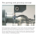
The parting and grooving concept Parting and grooving is a turning category of its own with a wide range of machining applications requiring dedicated tools (which can, to some extent, be used for general turning). To fully utilize the tools and get the best machining results there are some factors to consider. This user’s guide helps you to choose the right tool and insert for each parting and grooving operation and gives ideal cutting data start values.
Contents Simple and smart recommendations for parting and grooving operations................ 2 The different systems and when to use them................................................................. 4 Parting........................................................... 19 Parting of bars............................................ 20 Parting of tubes.......................................... 23 Grooving....................................................... Single cut grooving............................
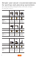
Simple and smart recommendations for parting and grooving operations More in-depth information, including practical hints is shown under each chapter. For cutting speed, see page 74. More info: Geometry: Grade: Cutting speed: Feed: More info: Geometry: Grade: Cutting speed: Feed: Parting of bar Parting of tube Grooving Page 20 Page 23 Page 27 CR GC2135 125 m/min 0.12 mm/r CM GC1125 125 m/min 0.12 mm/r GM GC1125 150 m/min 0.
3
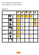
The different systems and when to use them External Parting (Cut-off) 4 CoroCut 2 CoroCut 1 CoroCut3 Q-Cut 151.2 Medium Deep Shallow Deep Q-Cut 151.
U-Lock 154.
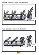
Internal grooving – min. hole diameter ≥4,2 ≥25 ≥12 ≥10 Min hole diameter 0,3 10 12 25 Face grooving – min.
Groove milling – min.
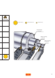
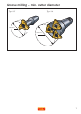
CoroCut 1- and 2-edge inserts – the first choice system Inserts This system is based on a patented Rail and V-shaped design which, together with a long insert, gives exceptional stability. These factors make it possible to run at higher cutting data and to achieve better productivity than any other system on the market. Insert Rail-shape V-shape Holder The inserts are available in different insert seat sizes covering inset widths from 1.5 mm up to 8 mm, having different corner radii.
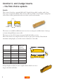
Geometries A large variety of geometries are available, dedicated to different applications and feed areas. Select the geometry after application and feed, see the table. CoroCut insert geometries Parting (Cut-off) Grooving Turning Finishing CF GF TF Medium CM GM TM Roughing CR Optimiser Sharp Profiling (Round) Aluminium profiling RM AM RO CS ER treated RS GE RE The first letter in the geometry name represents different application areas.
CoroCut3 – for shallow parting Intended for economical shallow parting in massproduction. The triangular shaped 3-edged inserts are available in widths 1–2 mm. The insert seat with a stable triangular shape allows cutting depths up to 6.4 mm. Inserts Available in 1, 1.5 and 2 mm widths and two insert seat styles, T for right hand and U for left hand holders. Depth limitations as below. Neutral inserts and front angled versions in 5° and 10° available. Tailor made inserts available from 0.5–3.20 mm.
Q-Cut 151.2 – for deep parting Q-Cut 151.2 is recommended for deep parting operations. The V-clamped 1-edged insert is ideal for parting operations. Together with parting blades, cutting depths of up to 55 mm are possible. Inserts Choose from a programme of insert widths from 2-8 mm. Geometries Dedicated geometries for parting 7E, 5E, 4E, 5F and 9E..
Q-Cut 151.3 – for internal machining and small diameter face grooving Q-Cut 151.3 is to be used for internal machining (diameters from 20–40 mm) and for facegrooving of smaller diameters (first cut diameter from 24–40 mm). The inserts are thinner in design in order to machine smaller diameters than the CoroCut 1and 2-edge inserts. To be used together with 151.3 bars and toolholders. Inserts A programme with widths from 2–8 mm.
CoroCut XS – for external small micro components CoroCut XS is a tangentially mounted system for precision machining in sliding head machines. CoroCut XS is available for external parting, grooving turning, backturning and threading applications. The extremely sharp cutting edges perform well at low feeds. Inserts Parting and grooving insert widths from 0.5–2.5 mm.
CoroCut MB – a system for internal grooving, threading and turning CoroCut MB has a front mounted exchangeable insert. Intended for internal machining in hole diameter from 10–25 mm. Sharp cutting edges for good results at low feeds. Boring bars in steel and carbide with through coolant to be used together with easy-fix clamping for overhang up to 6 x D. Inserts Grooving inserts in widths from 0.7–4 mm. Profiling, face grooving and preparting inserts are also available.
U-Lock 154.0 – for economical circlip grooving We recommend the U-Lock 3-edged inserts for both external and internal circlip grooving. Inserts A programme with widths from 1.10–4.15 mm.
CoroTurn XS – a system for internal precision machining CoroTurn XS has an insert in the form of a carbide-rod mounted in a holder. It is intended for precision machining in hole diameters from 3-12 mm, with extremely sharp cutting edges for good results at low feeds. Inserts Grooving insert widths from 0.78–2 mm, facegrooving, profiling and preparting inserts are also available. Threading inserts for metric, UN and Whitworth forms. Turning inserts for internal precision machining.
CoroMill 327 – grooving cutter for milling applications CoroMill 327 is intended for circlip grooving, T-slots milling and all other slot milling operations. CoroMill 327 is based on a sharp 3-edged insert together with a rigid screw clamping. The inserts produce grooves in holes of diameter ≥10 mm and width from 0.7–5.15 mm. Weldon shanks in steel and carbide for different overhangs are available.
CoroMill 328 - grooving cutter for milling applications CoroMill 328 is intended for circlip grooving, T-slots milling and all other slot milling operations. The CoroMill 328 has milling cutters for holes from min. 39 mm and 3-8 insert seats. Sharp inserts are available from 1.3-5.15 mm width.
Parting For parting we offer dedicated geometries with the CoroCut system. These geometries are designed to make the chip narrower than the groove and to give excellent chip control. The geometries are designed for high feed (CR), medium feed (CM) and low feed (CF). For extremely low feed and lowest possible cutting forces we offer the CS-geometry. For more information, see the Main catalogue. Radial feed Insert width (Ia), 3.0 m CS =R ecommended starting value. = First choice. 0.05 0.1 0.2 0.
Parting of bars When parting it is recommended to use an insert as narrow as possible in order to save material and minimise cutting forces. Long overhangs (ar) causing instability could result in tool failure and poor component quality. The recommended overhang should not exceed 8 x la (width of insert). Select correct width, geometry and system for parting of bars Component dia, mm <8 8–12 Insert width, Ia, mm Insert geometry Tool system Feed start value, mm/r 1 CM/CS CoroCut3 0.05 1.
Practical hints For a correct cutting process, be sure that the cutting edge height is maintained at a tolerance of ±0.1 mm of work piece centre. ±0.1 mm The most difficult sequence in parting to centre is when the component “drops” off. The cutting speed is extremely low, generating built-up edge on the insert corner. When the cut-off part of the component falls there is a large risk of chipping of the insert corners.
Pip free parting To avoid or minimise pips use right hand style or left hand style ground inserts with smallest possible front angle that gives an acceptable component. Inserts with 5° front angle are available in CF, CM and CR geometries. Inserts with 10° and 15° front angle are available in CS geometry. Note that a large front angle reduces pips, but will not produce a straight cut and give poorer surface finish and shorter tool life.
Parting-off tubes The width of the insert is recommended to be as narrow as possible in order to save material and minimise cutting forces. Long overhangs (ar) causing instability could result in tool failure and poor component quality. Select correct width, geometry and system for parting of tubes Component wall thickness, mm Insert width, la, mm Insert geometry Tool system Feed start value, mm/r <4 1 CM/CS CoroCut3 0.05 4–6 1.5 CM CoroCut 2&3 0.07 6–8 8–12 2 CM CoroCut 2 0.08 2.
Practical hints For correct cutting process, be sure that the cutting edge height is maintained at a tolerance of ±0.1 mm of work piece centre. ±0.1 mm • When parting into a drilled hole and insert enters the cone of the hole, the unbalanced cut may force the blade to deflect. This will create increased forces on one corner of the insert which may result in insert chipping and inconsistent tool life.
Burr free parting To avoid or minimise burrs use right or left hand style ground inserts with smallest possible front angle that gives an acceptable component. Inserts with 5° front angle are available in CF, CM and CR geometries. Inserts with 10° and 15° front angle are available in CS geometry. Note that a large front angle reduces burrs, but will not produce a straight cut and will give poorer surface finish and shorter tool life.
Parting – thin-walled tubes When parting off into thin-walled tubes ensure the lowest possible cutting forces are generated. Use inserts with smallest possible width and sharpest edges, i.e. CF or CS geometries. The precision ground CoroCut XS in combination with widths down to 0.7 mm gives the lowest cutting forces.
Grooving For grooving applications we offer dedicated geometries with the CoroCut system, e. g. GF, GM, TF and TM. These geometries are designed to give specific benefits in both radial and face grooving, and other machining methods such as external and internal multiple grooving and plunge turning. The different geometries are suitable for high or low feed machining. For circlip grooving, U-Lock 154.0 is the first choice for productive solutions. TM Radial feed Insert width (Ia), 3.
Single cut grooving Single cut grooving is the most economical and productive method of producing grooves and is possibe for use on insert widths up to 8 mm. The GF geometry precision insert has a width tolerance of ±0.02 mm. GF is our low feed choice (0.02–0.25 mm/r) and GM is intended for tougher machining e.g medium feed (0.04-0.30 mm/r). The TF geometry is designed with wipers on the side in order to generate extreme high surface quality on the side of the groove.
Practical hints When producing high quality grooves there is often a need for chamfered corners. One way to produce these is to use a standard width CoroCut GF insert and after the groove is made, use the corners of the insert to chamfer, see illustration A. A more productive way when machining large series is to order a Tailor Made insert with the exact form of the groove, see illustration B. Often cutting time can be reduced by up to 50% compared to the previous method.
Methods of turning grooves The most common applications for wide grooves or turning between shoulders are multiple grooving, plunge turning or ramping. All three methods are roughing operations and have to be followed by a separate finishing operation, see page 32. A rule of thumb is that if the width of the groove is smaller than the depth – multiple grooving should be used and vice versa for plunge turning. However for slender components ramping may be used.
Ramping The ramping method is recommended to avoid vibration and minimise radial forces when machining slender components. It also gives best swarf control and reduces notch wear in advanced materials. By using a round insert, RO or RM geometry, the feeding can be done faster, giving an even and higher productivity. Ramping, however, does double the number of cuts required. Ramping operation.
Cycle time comparison Multiple grooving Insert width 6 mm 32 sec 16 70 sec Direction of feed Feed 0.2 mm/r 56 sec 36 46 9 21 24 Plunge turning 37 sec 16 68 sec (7 passes) 36 Insert width 6 mm Depth of cut 3 mm Direction of feed Feed – radial – 0.2 mm/r Direction of feed Feed – axial – 0.3 mm/r 44 sec (3 passes) 46 9 21 24 Finishing of grooves Care must be taken when machining around the bottom radius of the groove.
Axial turning – surface finish Due to the wiper effect achieved in axial turning with CoroCut it is possible to generate a high quality surface finish. Ra value below 0.5 can be generated, and also high bearing ratio is achieved resulting in the elimination of a grinding operation. A B Comparison between CoroCut (A) and conventional turning tools (B). For comparison of surface finish achieved, see the following graph. Surface finish comparison Surface finish, Ra µm 4.0 3.
Recommended grade and cutting data First choice geometry for turning of grooves is TF for low feed and TM for higher feeds. Starting grade is GC1125. Cutting speed 150 m/min, radial feed 0.12 mm/r and axial feed 0.2 mm/r. Case story Machining specification Operation: Plunge turning Material: CMC 02.1 Machine: CNC turning lathe Toolholder: LF123H13-2525BM Insert: N123H2-0400-0004 Grade: GC1125 Roughing Ø 98 Ø 90 Finishing 12.
Circlip grooving For circlip grooving we have several main systems to choose from. For best economy use the three edged U-Lock 154.0 system (width 1.15–4.15 mm) for both internal and external operations. The second choice is CoroCut with GF geometry (width 1.85–5.15 mm) giving good productivity in external operations. U-Lock 154.0 insert and CoroCut insert in GF. For internal machining in small holes from 10 mm diameter and width 0.73–1.70 mm, the CoroCut is the first choice. For holes from 4.
Face grooving For components having an axial groove into the component it is important to choose the correct toolholder. The toolholder must be adapted to the bending radius of the groove and should therefore be curved. See Face grooving shank holders on page 61. CoroCut 1- and 2-edged grooving and turning inserts with GM, TF and RM geometries can be used. For small first cut diameters Q-Cut 151.3 with geometry 7G and 7P can be used. Normal feed methods should be used. SeeTurning of grooves on page 30.
Roughing When roughing the first cut should always be on the largest diameter and work inwards. Cut one gives chip control but no chip breaking and the width of cuts two and three should be 0.5–0.8 x width of the cutting edge. Chip breaking will now be operating at an acceptable level and thus, after the first insertion, the feed can be slightly increased. When retracting, offset the insert slightly from the inner edge of the groove.
Case story Ø 90 Ø 70 6 7 Tool life +100% Case story 2,0 ø25 ø17 2,8 Tool life +25% 38 Machining specification Operation: Face grooving Material: Stainless steel SS 2343, CMC 05.2 Machine: CNC turning lathe Toolholder: RF123K25-2525B-058BM Insert: N123K2-0600-0004-TF Grade: GC2135 Cutting data Cutting speed: Feed: Time in cut: Components: Productivity +44% Competitor 110 m/min 0.08 mm/r 0.18 min 390 pcs/edge Sandvik Coromant 110 m/min 0.16 mm/r 0.
Undercutting On many components there is a need for a grinding operation to achieve very close tolerances. In order to grind into a shoulder a clearance is needed. For this undercutting operation we recommend the use of round shaped inserts. For small clearance depths use CoroCut 1- or 2-edge inserts with RO or RM geometries and for larger clearance depths Q-Cut with 4U geometry is the best choice. Toolholders Use CoroCut toolholders type RX/LX with insert angle 7°, 45° or 70°.
Internal grooving Many components have an internal groove, most of them are close to the entrance into the hole e.g circlip grooves. The most common method to produce internal grooves is by radial grooving but also multiple grooving and plunge turning can be used, see page 30. CoroCut with dedicated geometries GF, GM, TF and TM to be used for internal operations. For small diameter bores down to 12 mm, the Q-Cut 151.3 with geometry 4G can be used.
Recommended grade and cutting data Starting grade GC1125. Cutting speed 125 m/min and feed 0.07 mm/r. Practical hints To avoid vibration the set up should have the shortest possible overhang with the lightest cutting geometry possible e. g. GF or TF. Vibration can also be avoided when machining large width grooves by making several insertions with a narrower insert and then make a finishing cut, see illustration A.
Profiling When machining components with complex shapes CoroCut offers great opportunities for rationalization. Since one single tool can be used instead of right and left hand conventional tools, the tool range is minimised. This results in fewer tool changes and more room in the turret. Using profiling inserts is often a good way of removing a lot of material in a short time. The stability of the CoroCut system offers strong possibility to use high cutting data.
Recommended grade and cutting data Starting grade GC1125. Cutting speed start value 150 m/min and feed start value 0.20 mm/r. Practical hints Wrap around is a problem that occurs with round inserts when plunging or profiling into corners. A large area of the insert is in contact all the time, creating high cutting pressure, so the feed needs to be reduced. HHowever, if reduced too much, vibration may occur.
Hard part machining For productivity increase without grinding Modern manufacturing technology places increasing demands on components to be made in one set-up, creating the need for machining hardened components. Modern cutting tool materials such as CBN (cubic boron nitride) act as a productivity booster when turning is used instead of grinding. For CoroCut 1-edge a small piece of CBN is brazed into a carbide body making it possible to groove and profile in hardened components.
Practical hints • Adjust centre height to correct position to get predictable tool life, see page 21. re • When machining pre-made grooves adjust horizontal position to equalize loads on the corners in order to get long tool life. If you have to machine in the bottom of the groove, reduce feed at the end of the cut. ≤ 0.5 re to reduce notch wear Pre-made grooved component. Case story Machining specification Operation: Grooving in hardened material Material: 20 Mn Cr 5, CMC 04.
Machining of aluminium and non-ferrous materials Many components are made in aluminium or other non-ferrous materials such as copper, brass, bronze but also plastic materials. A common feature with these materials is that a sharp edge and an open chip breaker is needed to be successful. In order to achieve these sharp edges, normally the edgeline has to be ground and the carbide needs to be either uncoated or with a thin coating.
HRSA and titanium grooving Heat resistant super alloys (HRSA) HRSA falls into three groups: nickel-based, iron-based and cobalt-based alloys. The physical properties and machining behaviour of each group varies considerably. Whether the metal is annealed or aged is particularly influential on the subsequent machining properties as the hardness varies from 150 to 440 HB. The machinability of HRSA is generally poor compared to both general steels and stainless steels.
CoroTurn HP – High pressure coolant In order to achieve chip-breaking in titanium alloys and to prolong tool life or to have increased productivity due to higher feeds we recommend to install high pressure coolant in your machine. Accurate coolant jets with laminar paralllel flow, are easily channeled through the Coromant Capto® coupling. The jets produce a hydraulic wedge, lifting the chip, reducing the temperature and improving the chip control. See the illustration.
Small part machining – sliding head machines The machines and the demand put on the tooling Small part machining and sliding head machines focus on components smaller than 32 mm in diameter, also known as Swiss machines. In these machines the material slides through the guide bush and is rotated by a second spindle that also pushes the material through the guide bush. The material is then acting as the z-axis in the machine and the tools stay close to the guide bush for maximum stability.
Choosing a tool system Work piece diameter range 32 16 8 2 CoroCut -S CoroCut XS Parting & grooving U-Lock -S CoroCut XS Threading CoroTurn 107 -S CoroTurn 111 CoroCut MB CoroCut XS Turning CoroTurn XS Internal machining External parting and grooving When choosing the appropriate parting tool there are some things to keep in mind. Depending on the material range and spindle size of the machine, tools of different styles should be selected with care. From 1.
From 12–32 mm diameter – CoroCut 1- and 2-edge are the ideal choice. Optimised holders with –S in the code indicate that they are designed for sliding head machines and have beneficial features such as angled insert clamping screw for easier clamping and blade reinforcement for better stability. These toolholders can also be used as a stop for the bar material. Holder with reinforced blade Recommended grade and cutting data Starting grade GC1125. Cutting speed 150 m/min and feed 0.08–0.1 mm/r.
CoroCut® XS for external grooving applications The CoroCut XS programme includes grooving inserts ranging in width from 0.5 mm, with and without a chip forming geometry, and also dedicated parting inserts from 0.7 mm wide. Turning, back turning and threading inserts can also be used in the same holder. Practical hints • CoroCut XS holders with -X in the code are designed for parting operations in sliding head machines with a sub-spindle where there is a limited tool space.
CoroTurn® XS for internal machining (Diameter area from 4.2–12 mm) For internal grooving CoroTurn XS is the ideal tooling family. The smallest bore possible for grooving with CoroTurn XS is 4.2 mm and is available with different insert widths. This tooling system has four insert sizes dedicated to different bore diameters. Also a range of various lengths is available for specific applications. However, the shortest possible overhang should always be the first choice.
The CoroTurn XS system includes different insert types for a wide range of applications i.e. grooving, profiling-grooving, face-grooving, pre-parting as well as turning, back-turning and threading. Grooving Turning Threading Grooving Grooving widths from 0.78–2 mm are available in different lengths for maximum stability, a very important feature when grooving. Profiling Round insert style for internal profiling and grooving available insert widths from 1–2 mm.
Pre-parting Special inserts are available for producing a 45° chamfer inside the bore before parting off the component, see the illustration. Grooving Insert width (la), mm =R ecommended starting value. 2.0 1.5 1.0 Feed (fn), mm/r 0,01 0,015 0,02 0,025 Recommended grade and cutting data Grade GC1025. Cutting speed 100 m/min, feed 0.015 mm/r.
Tool holding systems Parting and grooving sets high demands on accessibility since the inserts are often fed deep into the material. This means narrow machining and therefore the length of the tool increases as the diameter increases. Tools and tooling systems with high stability are therefore very important. For best productivity and economy we recommend the Coromant Capto system, offering exceptional accuracy and stability and a full programme of clamping units, cutting units and adaptors.
Clamping of CoroCut 1 and 2-edge inserts The insert clamping system has been designed to counteract high axial forces from both sides. For the smaller inserts (insert seats D–G) a V-profile clamping is used, but for larger inserts (insert seats H–L) the unique rail design adds superior stability to the insert clamping. The rail system should be first choice for profiling and turning applications (generating side forces) giving increased cutting data and highest stability.
Insert seats The programme is based on eight different insert seats depending on insert widths and geometries, see the table. CoroCut Insert seat size D E F G H J K L Insert widths, mm 1.5 2.0-2.4 2.4-3.2 3.0-4.0 4.0-5.0 5.0-6.4 6.0-7.1 7.9-8.0 Max cutting dept Ar max 12.9 19.0 18.9 18.8 23.7 23.6 23.5 28.4 Insert seat size to correspond with insert and toolholder. Q-Cut The Q-Cut system is based on only a V-shaped form, ideal for straight cutting forces, e.g.
Parting blades Intended for parting-off and deep grooving applications. For mounting in the machine a separate tool block must be used having normal shank sizes or Coromant Capto mounting. Practical hints • In order to avoid vibration and to achieve best tool life adjust the overhang, ar, of the blade to obtain the shortest possible overhang to suit the application. See drawing below. Max ar is 55 mm.
Practical hints • If using screw clamped reinforced blades check the cutting depth limitations in separate diagrams in Main catalogue. • Use the separate coolant adaptor for the tool block in order to achieve the best coolant supply. Reinforced blade. Solid toolholders Intended for grooving, turning and profiling applications in Coromant Capto and shank holder versions. Available in right hand, left hand and neutral style in short and long versions (ar).
Face grooving shank holders Intended for face grooving applications. Available in 0° and 90°, right and left hand style versions covering a large area of first cut diameters. 0° face grooving shank holder. Covers first cut diameter from 34–400 mm. All made in B-curved version, A-curved version to be ordered as Tailor Made or use the modular CoroCut SL system where both Aand B-curved blades are available. min. max. Q-Cut toolholder type 151.
Angled shank holders Intended for profiling and shallow undercutting applications. Available in 7°, 45° and 70°, right and left hand style versions. Developed specifically for aluminium rim machining. 70° angled holder. Shank holders for shallowgrooving These holders are universal for all shallow grooving and face grooving applications. They are often the only solution when Tailor Made inserts with complicated shapes are used.
Internal bars Intended for internal grooving applications. Available in right and left hand style bars from 16 to 50 mm diameter. These bars are equipped for internal coolant. Also 20° angled bars for internal profiling are available. Profiling bar. Grooving bar. Bars up to 25 mm diameter are cylindrical and designed to be used in EasyFix sleeves. Bars above 25 mm diameter have flats. Practical hints • Always mount the bars with shortest possible overhang in order to avoid vibration and deflection.
The CoroCut SL system A universal modular system. Intended mainly for internal grooving and external face grooving applications. Focused on Coromant Capto set-ups. • Consists of straight and face grooving blades for external and internal use. Blades for CoroCut, Q-Cut 151.3 and 151.2 available. - CoroCut for face grooving and grooving applications - CoroCut 3 for economical grooving - Q-Cut 151.3 for small internal diameters - Q-Cut 151.
Left hand 90° 0° Right hand 45° 0° 0° 45° 0° 90° Neutral Right hand Left hand A curve A curve 90° 90° B curve B curve Left hand tool = left hand adaptor+right hand cutting blade Left hand Left hand tool = left hand adaptor+left hand cutting blade CoroCut® SL blades Left hand Right hand tool = right hand adaptor+left hand cutting blade Neutral Other CoroTurn® SL - cutting heads Right hand Right hand tool = right hand adaptor+right hand cutting blade CoroCut® SL blades Right hand 65
Practical hints • Correct centre height settings It is essential when parting bars and groovingrelatively small diameters, that the centre height setting is maintained to a tolerance of ±0.1 mm. This has a major influence on tool life, cutting forces and pip size. ±0.1 mm • 90° mounting It is very important that the insert is mounted at 90° to the centre line of the workpiece in order to obtain perpendicular surfaces without scratch marks and to reduce the risk of vibration.
CoroCut MB for internal machining (Diameter area from 10 mm) CoroCut MB is a high precision grooving, turning and threading system for for machining min. 10 mm diameter holes. The edge line of the insert is sharp and together with a thin-layered coating it is suitable for internal machining. The insert is mounted with a screw from the front position in three grooves for safe and stable mounting. The system has two insert sizes dedicated to different bore diameter.
Grooving Grooving width from 0.7–3.0 for general grooving and circlip grooving. Profiling Round insert styles for internal profiling and grooving available in widths from 0.8–3.0 mm. Face grooving Face grooving is available for hole diameters from 12 mm and width from 1–3 mm. The maximum cutting depth for these inserts is 5 mm. Preparting Inserts for producing a 45° chamfer inside the bore before parting off the component are available. Grooving Insert width (la), mm 3.0 =R ecommended starting value.
CoroMill 327 – grooving cutter for milling applications CoroMill 327 is a sharp precision ground milling tool for grooving and threading machining into min 10 mm diameter holes. CoroMill 327 should be used for holes with circular interpolation but also for longitudinal milling. The insert is front mounted and positioned in three grooves for safe and stable mounting. The tool has four insert sizes for different hole diameters.
Recommended grade and cutting data Starting grade GC1025. Cutting speed 250m/min and feed per tooth fz 0.04 mm. For more cutting data, see the Main catalogue. Practical hints • Be aware, the CoroMill 327 inserts do not fit MB tools and vice versa. • For new toolholders, preload the tip-seat by mounting and or remounting the insert a few times prior to cutting.
Grades To cover all types of workpiece materials the CoroCut family has a variety of different carbide grades - from the highly wear resistant GC3115 to the toughest grade on the market GC2145. Cubic boron nitride (CB7015) and diamond (CD10) tipped inserts are also available. Unstable Toughness Wear resistance Stable conditions These grades have been developed to cope with the most complex of parting and grooving applications.
The different grades Grade GC3115 Based on a hard substrate, MT-CVD coated with TiCN-Al2O3 layer. A high wear resistant grade for grooving and turning applications under stable conditions. Also effective in hard steels. High cutting speeds. Grade GC4225 – first choice for cast iron Based on a hard gradient sintered substrate, MT-CVD coated with TiCN-Al2O3-TiN layer (black and yellow). An all-round grade for ISO-P and ISO-K with excellent combination of high wear resistance and good edge security.
Grade GC1005 A fine grained carbide substrate, PVD coated with TiAlN layer. Most suitable for roughing of aluminium. Grade H10 Uncoated carbide grade. Good edge sharpness for use in aluminium alloys and Heat Resistant Super Alloys (HRSA). Grade H13A – first choice for non-ferrous materials Uncoated carbide grade. Good wear resistance and toughness combined with edge sharpness. To be used in non-ferrous and titanium materials.
Cutting data recommendations • The recommendations are valid for use with cutting fluid. • Note! For internal grooving, face grooving and undercutting the speed should be reduced by 30–40%. ISO CMC Material Brinell GC3115 GC4225 GC1125 0,05-0,5 0,05-0,5 Feed fn’ mm/r 0,05-0,5 Cutting speed vc’ m/min P 01.2 02.2 Unalloyed Low-alloy ≤5% 150 275 M 05.11 05.21 15.51 Ferritic/ martensitic Austenitic Austenitic-ferritic (Duplex) 200 180 230 K 08.
GC2135 GC2145 0,05-0,5 0,05-0,5 180-75 155-70 160-65 140-60 145-65 165-70 115-55 130-50 140-55 105-45 H10 H13A 0,05-0,8 0,05-0,8 2250-225 630-65 1900-190 500-50 GC2135 GC2145 0,05-0,3 0,05-0,3 50-29 40-26 45-28 40-30 25-20 30-20 GC1105 ISO P = Steel, ISO M = Stainless steel, ISO K = Cast iron, ISO N = Aluminium and non-ferrous materials, ISO S = Heat resistant super alloys and titanium, ISO H = Hardened materials CMC = Coromant material classification 0,05-0,5 1) 2) 400-175 435-190
Wear mechanism – Trouble shooting Careful observations To achieve best possible economy regarding tool life, workpiece quality and optimised cutting data careful observations of the insert edge have to be made. At low speed built-up edge (BUE) and chipping are the main problems, at high speeds plastic deformation (PD), flank wear and crater wear are the problems. Built-up edge (BUE) Cause Solution • Cutting edge temperature too low. • Increase cutting speed and/ or feed. • Unsuitable geometry or grade.
Plastic deformation (PD) Cause Solution • Excessive temperature in cutting zone. • Reduce cutting speed and/or feed. • Unsuitable grade. • Choose more wear resistant grade. • Lack of coolant supply. • Improve coolant supply. Flank wear Cause Solution • Cutting speed too high. • Decrease cutting speed. • Too soft grade. • Choose more wear resistant grade. • Lack of coolant supply. • Improve coolant supply. Crater wear Cause Solution • Cutting speed too high. • Decrease cutting speed.
Tailor Made Grooves are often designed in many different shapes and dimensions depending on the working area. With Tailor Made tools you can increase the productivity and make it possible to generate grooves not possible with standard tools. We tailor inserts and toolholders to suit your specific component requirements. Contact your Sandvik Coromant representative for a quick quotation and competitive price and delivery.
Toolholders Both conventional toolholders and Coromant Capto are available in different styles and for different applications.
CoroCut insert blanks Straight blanks for “Do it yourself grinding” are available in 9 widths from 2.3–11.6 mm. These blanks have a flat top which allows grinding to many different shapes. Straight insert blank. 90° angled insert blank. 90º blanks in R/L versions are also available, mainly for use in the aerospace industry. When grinding, a standard toolholder is suitable as a grinding fixture, and recommended setting angles for the grinding wheel are shown in the drawings below.
Special products For even more complicated products our special tool design facility are able to produce inserts and toolholders to suit very specific requirements. Contact your Sandvik Coromant sales person for more details.
Head office: AB Sandvik Coromant SE-811 81 Sandviken, Sweden www.coromant.sandvik.com E-mail: info.coromant@sandvik.com C-1029:055 ENG/01 Printed on recycleable paper. Printed in Sweden, AB Sandvikens Tryckeri. © AB Sandvik Coromant 2008.