SERVICE & OPERATING MANUAL Certified Quality 1: PUMP SPECS Original Instructions Model S1F TROP EG 3: EXP VIEW 2: INSTAL & OP Non-Metallic Design Level 3 TELNI TPNF 4: AIR END Quality System ISO 9001 Certified Environmental Management System ISO 14001 Certified Warren Rupp, Inc. A Unit of IDEX Corporation 800 N. Main St., Mansfield, Ohio 44902 USA Telephone (419) 524.8388 Fax (419) 522.7867 SANDPIPERPUMP.COM dnuoS & hseM relffuM gninepmaD largetnI dradnatS noitpO relffuM noitpO ]343[ 05.
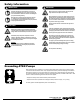
Safety Information IMPORTANT WARNING When used for toxic or aggressive fluids, the pump should always be flushed clean prior to disassembly. Read the safety warnings and instructions in this manual before pump installation and start-up. Failure to comply with the recommendations stated in this manual could damage the pump and void factory warranty. Before maintenance or repair, shut off the compressed air line, bleed the pressure, and disconnect the air line from the pump.
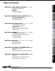
SECTION 5: WET END......................................17 • Diaphragm Drawings • Diaphragm Servicing SECTION 6: OPTIONAL CONFIGURATIONS.....19 • Solenoid Shifted Air Valve • Dual Port • Electronic Leak Detector Installation Instructions SECTION 7: WARRANTY & CERTIFICATES.....22 • Warranty • CE Declaration of Conformity - Machinery • ATEX Declaration of Conformity sandpiperpump . com s1fnmdl3sm-rev0316 2: INSTAL & OP 3: EXP VIEW 4: AIR END SECTION 4: AIR END........................................
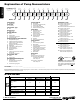
1: PUMP SPECS Explanation of Pump Nomenclature Your Model #: (fill in from pump nameplate) S __ ____ __ __ Pump Brand Pump Size Check Valve Design Level S XX X X Model #: Pump Brand S Check Valve Type Ball E PVDF Polypropylene Conductive Polypropylene Conductive PVDF I M S V Diaphragm/Check Valve Materials 4 B G M N V Y Z Santoprene/Santoprene PTFE Santoprene Backup/PTFE PTFE Pumping, PTFE-Santoprene Backup Driver/PTFE Santoprene Pumping/Santoprene Nitrile/Nitrile PTFE-Neoprene Backup/P
Performance S1F NON-METALLIC MODEL S1F Non-Metallic Performance Curve 5 (8.5) 10 (17) 7 100 1 00 P 6.8 80 AIR DISTRIBUTION VALVE • No-lube, no-stall design 5 HEAD SOLIDS-HANDLING • Up to .25 in. (6mm) HEADS UP TO • 100 psi or 231 ft. of water (7 bar or 70 meters) 4 SI (5 60 3 SI (4 40 MAXIMUM OPERATING PRESSURE • 100 psi (7 bar) 0 0 SHIPPING WEIGHT • Polypropylene 42 lbs. (19kg) • PVDF 54 lbs. (24kg) I (1.36 0 5 10 30 (51) Bar) 35 (59.5) 40 (68) 45 (76.5) 2 Bar 20 PS 0 25 (42.
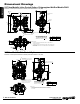
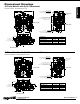
1: PUMP SPECS Dimensional Drawings S1F Non-Metallic Inline Ported Option- Polypropylene Wet End Models ONLY Dimensions in inches (metric dimensions in brackets). Dimensional Tolerance .125" (3mm). A DISCHARGE PORT (OPTIONAL) 1" FNPT 4.96 126 19.94 506 2X 2.15 55 DISCHARGE PORT 1" FNPT AIR INLET 1/2 FNPT 18.18 462 17.12 435 9.81 249 2.50 64 .
S1F Non-Metallic with Spill Containment Dimensions in Inches.
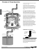
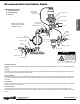
Principle of Pump Operation Air-Operated Double Diaphragm (AODD) pumps are powered by compressed air or nitrogen. 2: INSTAL & OP The main directional (air) control valve ① distributes compressed air to an air chamber, exerting uniform pressure over the inner surface of the diaphragm ②. At the same time, the exhausting air ③ from behind the opposite diaphragm is directed through the air valve assembly(s) to an exhaust port ④.
Recommended Installation Guide Available Accessories: 1. Surge Suppressor 2. Filter/Regulator 3.
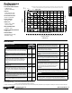
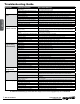
Troubleshooting Guide Symptom: Pump Cycles Once 2: INSTAL & OP Pump Will Not Operate / Cycle Pump Cycles and Will Not Prime or No Flow Pump Cycles Running Sluggish / Stalling, Flow Unsatisfactory Product Leaking Through Exhaust Premature Diaphragm Failure Unbalanced Cycling Potential Cause(s): Deadhead (system pressure meets or exceeds air supply pressure). Air valve or intermediate gaskets installed incorrectly. Bent or missing actuator plunger. Pump is over lubricated.
Composite Repair Parts Drawing Torque: 140 in. lbs. 64 63 INLINE DISCHARGE MANIFOLD OPTION Torque: 140 in. lbs. Torque: 200 in. lbs. 3: EXP VIEW Torque: 180 in. lbs. Torque: 320 in. lbs. Torque: 200 in. lbs. Torque: 160 in. lbs.
Composite Repair Parts List Part Number 031-140-000 031-140-001 031-140-002 031.140.
000 ����Assembly, sub-assembly; and some purchased items 010 ����Cast Iron 015 ����Ductile Iron 020 ����Ferritic Malleable Iron 080 ����Carbon Steel, AISI B-1112 110 �����Alloy Type 316 Stainless Steel 111 �����Alloy Type 316 Stainless Steel (Electro Polished) 112 �����Alloy C 113 �����Alloy Type 316 Stainless Steel (Hand Polished) 114 �����303 Stainless Steel 115 �����302/304 Stainless Steel 117 �����440-C Stainless Steel (Martensitic) 120 ����416 Stainless Steel (Wrought Martensitic) 148 ����Hardcoat Anod
Spill Containment Options Virgin PTFE Equipped Pumps IMPORTANT Read these instructions completely, before installation and start-up. It is the responsibility of the purchaser to retain this manual for reference. Failure to comply with the recommendations stated in this manual will damage the pump, and void factory warranty. 3: EXP VIEW Note: Item 45 The diaphragm is to be installed with the convex side facing toward the outer chambers.
Spill Containment Servicing Step 1: With the unit removed from service. Remove each bottom boss plug (item 51). Drain the fluid from spill containment chambers. With manifolds and outer chambers removed, remove diaphragm assemblies from diaphragm rod. DO NOT use a pipe wrench or similar tool to remove assembly from rod. Flaws in the rod surface may damage bearings and seal. Soft jaws in a vise are recommended to prevent diaphragm rod damage. Step 1.A: NOTE: Not all inner diaphragm plates are threaded.
Air Distribution Valve Assembly 1-J 1-G 1-F 1-D 1-E 1-G 1-A 1-G NOTE: CHECK GAP AFTER ASSEMBLY TO INSURE COMPLETE INSTALLATION OF RETAINING RING 1-B 4: AIR END Air Valve Assembly Parts List 1-E 1-H Air Distribution Valve Servicing See repair parts drawing, remove screws. Step 1: Remove staple retainer (1-H). Step 2: Remove end cap (1-E). Step 3: Remove spool part of (1-A) (caution: do not scratch). Step 4: Press sleeve (1-A) from body (1-B). Step 5: Inspect O-Ring (1-H) and replace if necessary.
Air Valve with Stroke Indicator Assembly Note: Stroke Indicator is standard on Spill Containment models 1-J 1-G 1-F 1-D 1-E 1-G 1-M 1-C 1-A 1-K 1-C NOTE: CHECK GAP AFTER ASSEMBLY TO INSURE COMPLETE INSTALLATION OF RETAINING RING 1-B Air Valve Assembly Parts List 1-M 1-G 1-H Air Distribution Valve Servicing See repair parts drawing, remove screws. Step 1: Remove staple retainer (1-H). Step 2: Remove end cap (1-E), bumper (1-C). Step 3: Remove spool part of (1-A) (caution, do not scratch).
Pilot Valve Assembly 3-A 4: AIR END 3-F 3-B 3-E 3-C Pilot Valve Servicing With Pilot Valve removed from pump. Step 1: Remove snap ring (3-F). Step 2: Remove sleeve (3-B), inspect O-Rings (3-C), replace if required. Step 3: Remove spool (3-D) from sleeve (3-B), inspect O-Rings (3E), replace if required. Step 4: Lightly lubricate O-Rings (3-C) and (3-E).
Intermediate Assembly Drawing 4 34 6 Intermediate Assembly Drawing Step 1: Remove plunger, actuator (30) from center of intermediate pilot valve cavity. Step 2: Remove Ring, Retaining (32), discard. Step 3: Remove bushing, plunger (6), inspect for wear and replace if necessary with genuine parts. Step 4: Remove O-Ring (27), inspect for wear and replace if necessary with genuine parts. Step 5: Lightly lubricate O-Ring (27) and insert into intermediate.
Diaphragm Service Drawing with Overlay Torque: 320 in. lbs. OVERLAY OPTION OVERLAY OPTION 5: WET END Diaphragm Service Drawing, Non-Overlay Torque: 320 in. lbs. Torque: 320 in. lbs. ONE-PIECE BONDED OPTION Field conversion kit 475-258-000 available for conversion from PTFE Overlay to One-Piece bonded Diaphragm ONE-PIECE BONDED OPTION Part 286-115-000 612-220-150 Description One-Piece Diaphragm Plate, Inner Diaphragm 17 • Model S1F Non-Metallic Qty 2 2 sandpiperpump .
Diaphragm Servicing Step 1: With manifolds and outer chambers removed, remove diaphragm assemblies from diaphragm rod. DO NOT use a pipe wrench or similar tool to remove assembly from rod. Flaws in the rod surface may damage bearings and seal. Soft jaws in a vise are recommended to prevent diaphragm rod damage. Step 1.A: NOTE: Not all inner diaphragm plates are threaded. Some models utilize a through hole in the inner diaphragm plate.
Solenoid Shifted Air Valve 56 Wiring Diagram #2 Terminal Neutral (Negative) 3rd Terminal for ground 58 57 #1 Terminal Power (Positive) 59 60 56 Solenoid Shifted Air Valve Parts List Solenoid Shifted Operation 6: OPTIONAL The Solenoid Shifted SANDPIPER has a solenoid operated, air distribution valve in place of the standard SANDPIPER’s pilot operated, air distribution valve. Where a pilot valve is normally utilized to cycle the pump’s air distribution valve, an electric solenoid is utilized.
Dual Port Option DUAL PORTING OPTIONS Several dual porting options are possible. The pump can be converted to a dual port arrangement on both the suction and the discharge ends. The porting can be configured to a single suction and a dual discharge. The porting can be changed to a dual suction and a single discharge. The above changes are possible because the porting flange of the elbows (items 18 and 19) are designed to mate with standard 125# ANSI style 4-bolt, 1" pipe flanges.
Leak Detection Options Drawing 44 710-014-330 Self-tapping Screws (Qty of 2) 53 54 52 49 MUFFLER CAP For pumps 530-028-550 Enclosed Muffler LEAK DETECTION OPTION A (ELECTRONIC) For pumps with Alternate Mufflers 6: OPTIONAL Follow instructions found elsewhere in this manual, “Filling the Spill Containment Chambers” when installing leak detectors.
5 - YEAR Limited Product Warranty Warren Rupp, Inc. (“Warren Rupp”) warrants to the original end-use purchaser that no product sold by Warren Rupp that bears a Warren Rupp brand shall fail under normal use and service due to a defect in material or workmanship within five years from the date of shipment from Warren Rupp’s factory. Warren Rupp brands include Warren Rupp ®,SANDPIPER ®, MARATHON ®, PortaPump ®, SludgeMaster™ and Tranquilizer ®. ~ See sandpiperpump.
EC / EU Declaration of Conformity The objective of the declaration described is in conformity with the relevant Union harmonisation legislation: Directive 94/9/EC (until April 19, 2016) and Directive 2014/34/EU (from April 20, 2016). Manufacturer: Warren Rupp, Inc. A Unit of IDEX Corportion 800 North Main Street P.O.