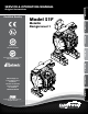
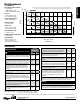
06.29 8.37 212.71 Model S1F Metallic Design Level 1 .38 MOUNTING HOLES 9.53 12.03 305.56 1.22 30.96 .41 System Quality 10.32 ISO 9001 Certified SUCTION PORT 6.731" NPT 171.07 BOTTOM VIEW 5.31 135 AIR INLET 1/2 NPT 6.39 162.31 1.63 41.28 4: AIR END 89.81 4.19 106.43 3.93 99.89 7.44 188.98 Certified Quality 3.54 4X DISCHARGE PORT 1" NPT 2: INSTAL & OP 4.18 Original Instructions 3: EXP VIEW SERVICE & OPERATING MANUAL 1: PUMP SPECS 9.09 230.80 2.00 50.80 5.
Safety Information IMPORTANT WARNING When used for toxic or aggressive fluids, the pump should always be flushed clean prior to disassembly. Read the safety warnings and instructions in this manual before pump installation and start-up. Failure to comply with the recommendations stated in this manual could damage the pump and void factory warranty. Before maintenance or repair, shut off the compressed air line, bleed the pressure, and disconnect the air line from the pump.
SECTION 5: WET END......................................18 • Diaphragm Drawings • Diaphragm Servicing SECTION 6: OPTIONAL CONFIGURATIONS.....20 • Solenoid Shifted Air Valve SECTION 7: WARRANTY & CERTIFICATES.....21 • Warranty • CE Declaration of Conformity - Machinery • ATEX Declaration of Conformity • ATEX Summary of Markings sandpiperpump . com s1fmdl1sm-rev0614 2: INSTAL & OP 3: EXP VIEW 4: AIR END SECTION 4: AIR END........................................
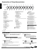
1: PUMP SPECS Explanation of Pump Nomenclature Your Model #: (fill in from pump nameplate) S __ ____ __ __ Pump Brand Pump Size Check Valve Design Level S XX X X Model #: Pump Brand S __ __ Wetted Diaphragm/ Check Valve Non-Wetted Material Check Valve Seat Material X A I Y 1F 1" X Z Design Level Porting Options Ball Aluminum Cast Iron Stainless Steel Alloy C Unpainted Aluminum __ ____ Porting Options Pump Style Pump Options Kit Options X X X XX Kit Options Pump Style S
Performance S1F METALLIC 5(8.5) 100 25(42.5) 80 80 P SI (5 5 HEAD AIR DISTRIBUTION VALVE • No-lube, no-stall design SOLIDS-HANDLING • Up to .25 in. (6mm) HEADS UP TO • 125 psi or 289 ft. of water (8.6 Kg/cm2 or 86 meters) 4 3 10(17) PSI (6.8 15(25.5) Bar) 20(34) 60 60 PS ar) DISPLACEMENT/STROKE • .11 Gallon / .42 liter MAXIMUM OPERATING PRESSURE • 125 psi (8.6 bar) 40 SHIPPING WEIGHT • Aluminum 28 lbs. (13kg) • Cast Iron 46 lbs. (21kg) • Stainless Steel 43 lbs.
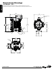
1: PUMP SPECS Dimensional Drawings S1F Metallic - NPT Dimensions in inches (mm dimensions in brackets). Dimensional Tolerance:±1/8" (± 3mm) The dimensions on this drawing are for reference only. A certified drawing can be requested if physical dimensions are needed. 10.25 260.35 10.25 260.35 9.09 230.80 9.09 230.80 5.13 130.18 5.13 130.18 12.88 327.09 12.88 327.09 AIR INLET 1/2 NPT AIR INLET 1/2 NPT 12.03 305.56 12.03 305.56 6.40 162.43 6.40 162.43 .41 10.32 .41 10.
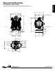
Dimensional Drawings S1F Metallic - ANSI Flange 1: PUMP SPECS Dimensions in inches (mm dimensions in brackets). Dimensional Tolerance:±1/8" (± 3mm) The dimensions on this drawing are for reference only. A certified drawing can be requested if physical dimensions are needed. 9.10 231.14 10.25 260.35 3.87 98.17 5.13 130.18 4.64 117.73 DISCHARGE PORT 1" 150# ANSI RF FLANGE 14.04 356.50 16.04 407.30 SUCTION PORT 1" 150# ANSI RF FLANGE 1" NPT EXHAUST PORT 3.22 81.76 2.00 50.80 2.00 50.80 .13 3.
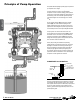
Principle of Pump Operation Air-Operated Double Diaphragm (AODD) pumps are powered by compressed air or nitrogen. 2: INSTAL & OP The main directional (air) control valve ① distributes compressed air to an air chamber, exerting uniform pressure over the inner surface of the diaphragm ②. At the same time, the exhausting air ③ from behind the opposite diaphragm is directed through the air valve assembly(s) to an exhaust port ④.
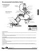
Recommended Installation Guide Available Accessories: 1. Surge Suppressor 2. Filter/Regulator 3.
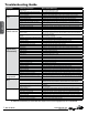
Troubleshooting Guide Symptom: Pump Cycles Once 2: INSTAL & OP Pump Will Not Operate / Cycle Pump Cycles and Will Not Prime or No Flow Pump Cycles Running Sluggish / Stalling, Flow Unsatisfactory Product Leaking Through Exhaust Premature Diaphragm Failure Unbalanced Cycling Potential Cause(s): Deadhead (system pressure meets or exceeds air supply pressure). Air valve or intermediate gaskets installed incorrectly. Bent or missing actuator plunger. Pump is over lubricated.
Composite Repair Parts Drawing 8 18 11 4 Torque: 90 in/lbs 17 31 25 20 7 21 9 26 30 28 16 1 12 5 3: EXP VIEW 2 3 29 27 13 6 Torque: 90 in/lbs 10 23 14 32 OPTIONAL MUFFLER 24 14 15 Torque: 350 in/lbs 2 24 29 Torque: 450 in/lbs with PTFE overlay diaphragms OPTIONAL OVERLAY 22 19 29 30 22 9 OPTIONAL METALLIC SEAT Service & Repair Kits 476-228-000 Air End Kit (Aluminum Center) 476-194-635 Wet End Kit 476-201-000 Air End Kit 476-194-654 Wet End Kit Seals, O-Ri
3: EXP VIEW Composite Repair Parts List Item Part Number Description Qty 1 031.179.000 Air Valve Assembly (Cast Iron Centers Only) 1 031.146.000 Air Valve Assembly (Stroke Indicator) 1 031.147.000 Air Valve Assembly (Stroke Indicator) 1 031.183.000 Air Valve Assembly 1 031.183.001 Air Valve Assembly (W/Stainless Steel Hardware) 1 031.173.000 Air Valve Assembly (W/ Aluminum centers only) 1 031.173.
000 ����Assembly, sub-assembly; and some purchased items 010 ����Cast Iron 015 ����Ductile Iron 020 ����Ferritic Malleable Iron 080 ����Carbon Steel, AISI B-1112 110 �����Alloy Type 316 Stainless Steel 111 �����Alloy Type 316 Stainless Steel (Electro Polished) 112 �����Alloy C 113 �����Alloy Type 316 Stainless Steel (Hand Polished) 114 �����303 Stainless Steel 115 �����302/304 Stainless Steel 117 �����440-C Stainless Steel (Martensitic) 120 ����416 Stainless Steel (Wrought Martensitic) 148 ����Hardcoat Anod
Air Distribution Valve Assembly 4: AIR END (Use With Aluminum Centers Only) Air Distribution Valve Servicing See repair parts drawing, remove screws. Step 1: Remove hex cap screws (1-F). Step 2: Remove end cap (1-E) and bumper (1-C). Step 3: Remove spool part of (1-B) (caution: do not scratch). Step 4: Press sleeve (1-B) from body (1-A). Step 5: Inspect O-Rings (1-D) and replace if necessary. Step 6: Lightly lubricate O-Rings (1-D) on sleeve (1-B). Step 7: Press sleeve (1-B) into body (1-A).
4: AIR END Air Distribution Valve Assembly Air Distribution Valve Servicing See repair parts drawing, remove screws. Step 1: Remove hex cap screws (1-F). Step 2: Remove end cap (1-E) and bumper (1-C). Step 3: Remove spool part of (1-B) (caution: do not scratch). Step 4: Press sleeve (1-B) from body (1-A). Step 5: Inspect O-Rings (1-D) and replace if necessary. Step 6: Lightly lubricate O-Rings (1-D) on sleeve (1-B). Step 7: Press sleeve (1-B) into body (1-A).
Air Distribution Valve Assembly (Use With Cast Iron Centers Only) 1-F 1-D 1-D 1-C 1-E 1-B 1-B 1-A * Note: cannot be used with integral muffler Option 0. 1-C 4: AIR END 1-D 1-E 1-F Air Distribution Valve Servicing See repair parts drawing, remove screws. Step 1: Remove hex cap screws (1-F). Step 2: Remove end cap (1-E) and bumper (1-C). Step 3: Remove spool part of (1-B) (caution: do not scratch). Step 4: Press sleeve (1-B) from body (1-A).
Air Distribution Valve Assembly (For NON-ATEX Cast Iron Centers) 1-J 1-H 1-G 1-D 1-G 1-E 1-F 1-C 1-A 1-A NOTE: CHECK GAP AFTER ASSEMBLY TO INSURE COMPLETE INSTALLATION OF RETAINING RING 1-G 1-E 4: AIR END 1-B 1-C 1-H Air Distribution Valve Servicing See repair parts drawing, remove screws. Step 1: Remove end cap retainer (1-H). Step 2: Remove end cap (1-E). Step 3: Remove spool part of (1-A) (caution: do not scratch). Step 4: Press sleeve (1-A) from body (1-B).
Air Valve with Stroke Indicator Assembly 1-B 1-B 4: AIR END NOTE: CHECK GAP AFTER ASSEMBLY TO INSURE COMPLETE INSTALLATION OF RETAINING RING 1-A Air Distribution Valve Servicing See repair parts drawing, remove screws. Step 1: Remove end cap retainer (1-H). Step 2: Remove end cap (1-E), bumper (1-C). Step 3: Remove spool part of (1-B) (caution, do not scratch). Step 4: Press sleeve (1-B) from body (1-A). Step 5: Inspect O-Rings (1-G) and replace if necessary.
4: AIR END Pilot Valve Assembly Pilot Valve Servicing With Pilot Valve removed from pump. Step 1: Remove snap ring (4-F). Step 2: Remove sleeve (4-B), inspect O-Rings (4-C), replace if required. Step 3: Remove spool (4-D) from sleeve (4-B), inspect O-Rings (4E), replace if required. Step 4: Lightly lubricate O-Rings (4-C) and (4-E). Reassemble in reverse order. Pilot Valve Assembly Parts List Item 4 4-A 4-B 4-C 4-D 4-E 4-F Part Number 095.110.000 095.095.157 755.052.000 560.033.360 775.055.000 560.023.
Intermediate Assembly 4: AIR END 28 Intermediate Assembly Drawing Step 1: Remove plunger, actuator (25) from center of intermediate pilot valve cavity. Step 2: Remove Ring, Retaining (26), discard. Step 3: Remove bushing, plunger (7), inspect for wear and replace if necessary with genuine parts. Step 4: Remove O-Ring (21), inspect for wear and replace if necessary with genuine parts. Intermediate Assembly Parts List Item 5 7 21 25 26 28 Part Number 114.025.157 114.025.010 135.036.506 560.
Diaphragm Service Drawing, with Overlay 450 in.lbs. for Overlay diaphragms Diaphragm Service Drawing, Non-Overlay 5: WET END 350 in.lbs. for PTE and elastomer diaphragms One-Piece Bonded *Diaphragm Service Drawing 14 *Available For Field Conversion From Overlay To One-Piece Bonded Diaphragm Kits: Kit: 2 2 sandpiperpump . com s1fmdl1sm-rev0614 475.250.000 286.112.000 612.218.
Diaphragm Servicing Step 1: With manifolds and outer chambers removed, remove diaphragm assemblies from diaphragm rod. DO NOT use a pipe wrench or similar tool to remove assembly from rod. Flaws in the rod surface may damage bearings and seal. Soft jaws in a vise are recommended to prevent diaphragm rod damage. Step 1.A: NOTE: Not all inner diaphragm plates are threaded. Some models utilize a through hole in the inner diaphragm plate.
Solenoid Shifted Air Valve 36 37 33 Wiring Diagram 3rd Terminal for ground. #2 Terminal Neutral (Negative) #1 Terminal Power (Positive) 35 34 37 33 Solenoid Shifted Air Valve Parts List (Includes all items used on Composite Repair Parts List except as shown) Solenoid Shifted Air Distribution Valve Option Item 33 34 Part Number 893.097.000 219.001.000 219.004.000 219.002.000 219.003.000 35 241.001.000 241.003.000 36 170.045.330 37 618.050.
Written Warranty 5 - YEAR Limited Product Warranty Quality System ISO 9001 Certified • Environmental Management Systems ISO 14001 Certified Warren Rupp, Inc. (“Warren Rupp”) warrants to the original end-use purchaser that no product sold by Warren Rupp that bears a Warren Rupp brand shall fail under normal use and service due to a defect in material or workmanship within five years from the date of shipment from Warren Rupp’s factory.
EC Declaration of Conformity In accordance with ATEX Directive 94/9/EC, Equipment intended for use in potentially explosive environments. Manufacturer: Warren Rupp, Inc.®, A Unit of IDEX Corportion 800 North Main Street, P.O. Box 1568, Mansfield, OH 44902 USA EN 60079-25: 2011 For pumps equipped with Pulse Output ATEX Option Quality B.V.